Parallel connection of speakers. Are the speakers connected in parallel or in series? That is the question
If you're building a loud front with big amount speakers, then you will have to connect them together in order to connect two or more speakers to one amplifier channel. Of course, no one puts one din per channel, it’s just expensive.
If, for example, you install 4 pairs of speakers, of course it is better to connect them in pairs, it will be more reasonable, and the power will be higher, and you will need one 4-channel amplifier. As long as the total resistance of the dins connected in parallel to one channel is not less than the tolerance (for example, 2 Ohms or 1 Ohm), everything is fine. But when they want more speakers, people start combining switching methods. For example, four 4-ohm speakers are switched in series in pairs and the pairs are connected in parallel. The total resistance is 4 Ohms, 4 speakers are connected per channel. Everything seems to be fine. And to make things really good, another 4-ohm speaker is switched in parallel, then the total resistance is 2 ohms and 5 speakers are connected to each channel.
There are also more witty combinations. For example, three speakers are placed on a channel. One 8 ohm, and two 4 ohm. The four-ohm ones are connected in series and an eight-ohm one is connected to them in parallel. The sum is again 4 Ohms, from a mathematical point of view everything is fine.
But there are nuances. The trouble is that the power between the speakers is not distributed evenly. Some are overloaded, others are resting.
To figure out what's what here, you need a little math.
Let's say that we have two speakers with resistance R 1 and R 2 and they are both connected to the same amplifier channel in series or parallel. The amplifier power P will be distributed between the speakers:
P=P 1 +P 2
where P 1 and P 2 are the powers that “arrive” on the dynes.
What is the ratio of these powers? How different can they be?
Serial connection
If the speakers are connected in series, then flow through them total current. The power dissipated by them will be I 2 R 1 and I 2 R 2, respectively
P=I 2 R 1 +I 2 R 2
where I is the total current flowing through both speakers.
From the last equation it is clearly clear that the power will be dissipated more on the dyne that has greater resistance. That is, if we connect an 8-ohm and a 4-ohm speaker in series, the 8-ohm speaker will be loaded more. This sounds strange to many, but it is true. Therefore, I would categorically not recommend connecting speakers with different resistances in series. In fact, only one will work.
What happens if the speakers have the same impedance? In theory, the power should be distributed evenly. But there is one thing that is almost never written about - the reactive component of the total resistance. The impedance is not constant, it depends on the frequency of the signal supplied to the speaker coil. As the frequency increases, the impedance increases, and the inductance of the voice coil is to blame. Everyone knows this.
But there is another component of impedance that is very important and never mentioned. The fact is that a speaker is not just a coil with inductance, it also moves in a magnetic field. Essentially, any speaker of a popular design is a reciprocating electrical machine. Electric motor. Like almost all electric machines, it is reversible. This means that during operation the speaker generates some EMF which is expressed in an increase in impedance - total resistance. The greater the amplitude of the oscillations, the greater the total resistance will be. The increase in impedance is not large over almost the entire audio range and does not have a noticeable effect. Apparently that's why they don't remember her. But near the speaker's natural resonant frequency, the magnitude of the back-EMF is so large that the associated increase in impedance can be 10-20 times greater than all other components of the impedance.
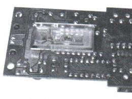
Look at the picture. It shows the real impedance characteristic of the Oris GR-654 speaker. On resonant frequency its total resistance is 48 ohms. This is simply a colossal amount. It is more than 10 times the total resistance over the operating range.
Why did we talk about this phenomenon at all?
The fact is that when you buy a pair of speakers, they are the same only formally. In fact, the speakers, even taken out of the same box, are slightly different. In some places the coils are a couple of turns larger, in others the movement is a little harder or softer, etc. In any case, the dynamics will oscillate with different amplitudes. Then one will have more resistance than the other. The power will not be distributed evenly. And if the speakers operate near resonance, and this is almost always the case, the situation will not be pleasant at all. The speaker with more resistance will be loaded more. A little. The vibration amplitude of its diffuser will be slightly larger. Accordingly, the resistance will increase even more, which will further increase the imbalance in power, which will increase the resistance even more, and so on. But we remember that near resonance the resistance can increase 10 times. One of the speakers will take care of everything. This turns out to be a classic version of the system with a positive feedback. One of the speakers will quickly overload, while the other will rest. There can be no talk of normal sound. You will have to “cut” the dynes at frequencies significantly higher than the resonance frequency.
In general, I would not recommend connecting speakers in series. With midrange drivers and tweeters this still works out somehow, but with subwoofers it’s a problem. They always operate in an area of strong impedance unevenness. Therefore, if two speakers are connected in series (namely speakers, not coils of one speaker, this is important), only one works and is quickly overloaded, and the second dangles like a passive radiator. I have never seen a normally working subwoofer with two speakers connected in series. Even by eye it is clear that their diffusers do not vibrate in phase. This is often attributed to the wrong case, although it has absolutely nothing to do with it.
The attached video clearly shows how two Oris LW-D2.12 speakers connected in series work completely at odds. Not in antiphase, as it might seem at first glance, but out of tune. This is due to the fact that at large oscillation amplitudes, a large imbalance in the load between the speakers develops.
Parallel connection.
If the speakers are connected in parallel, the currents flow through them are different, but the signal across them is exactly the same. Therefore, the power distribution equation can be written in another form:
P=U 2 /R 1 +U 2 /R 2
where U is the signal supplied to the speakers.
This equation shows that the lower the speaker's resistance, the more power it dissipates. If you connect an 8-ohm and a 4-ohm speaker in parallel, the 4-ohm speaker will be loaded primarily. The other will be in a relaxed state.
If we connect speakers with the same impedance, the power distribution between them will be completely different. Here there will be a classical system with negative feedback. That is, the greater the resistance of the speaker, the less power will be dissipated on it. The system will operate absolutely stably, the power will be distributed almost equally. You can even include different sized speakers different manufacturers, there will be no imbalance.
Generally parallel connection the best option for any speakers. The only one for subs.
Should I combine parallel and serial connections?
I would not recommend it, especially if speakers with different resistances are connected. For example, if you connect two 4-ohm speakers in series and another 8-ohm speaker, the power will be distributed extremely unevenly across them. At best, 50% for 8-ohm, and 25% for 4-ohm.
In principle, it is possible to connect speakers in series/parallel with the same resistance, but it is worth remembering that there can be a large imbalance in power between those connected in series.
How to connect speakers?
Definitely in parallel, and everything will be fine for you. Speakers of any type and in any quantity should be connected in parallel, if of course it makes sense. Of course, the total resistance must be within the tolerance of the amplifier. It is worth connecting more than two speakers per channel only in this case. if you have a really powerful amplifier, 500 or more watts per channel. No matter how you connect the speakers, the amplifier's power will be distributed across them. And if your amplifier has 100-150 W, you shouldn’t expect much output. Two dynes in parallel - that's all it will be. And the output will be noticeably higher, and you will get everything out of the amplifier.
Series, parallel and mixed speaker connection

The most important thing when connecting speakers is to make the connection so that neither speaker is overloaded. Overloading threatens to damage the speaker.
It is important to understand that the speaker can be supplied with power either less than or equal to the rated power for which it is, in fact, designed. IN otherwise, sooner or later even the highest quality speaker will fail due to overload.
It is clear that before connecting the speakers you need to define them:
Rated power ( W, W);
Active resistance of the voice coil ( Ohm, Ω ).
All this, as a rule, is indicated on the magnetic system of the speaker, or on the basket.

1W means 1W, 4Ω is the resistance of the voice coil.

Speaker brand - 3GDSH-16. The first number 3 is the rated power, 3 W. Next to it is the signature - 8 Ohm, coil resistance.
Sometimes they don’t indicate it, but you can recognize it by the markings.

Midrange speaker 15GD-11-120. Rated power - 15 W, coil resistance - 8Ω.
Speaker connection. Example.
Let's start with the basics, so to speak - clear examples. Let's imagine that we have a 6-watt audio power amplifier (AMP) and 3 speakers. Two 1 W speakers (coil resistance 8 Ω each) and one 4 W speaker (8 Ω). The challenge is to connect all 3 speakers to the amplifier.
Let's look at an example first unfaithful connections of these speakers. Here is a visual drawing.

As you can see, the resistance of all three speakers is the same and equals 8 Ω. Since this is a parallel connection of speakers, the current will be divided equally between the 3 speakers. At maximum amplifier power (6 W), each speaker will receive 2 W of power. It is clear that 2 out of 3 speakers will be overloaded - those whose rated power is 1 W. It is clear that such a connection diagram no good.
If the amplifier outputted only 3 W sound power, then such a circuit would be suitable, but a 4 W speaker would not work at full strength - “filonil”. Although this is not always critical.
Now let's take an example of the correct connection of the same speakers. Let's use the so-called mixed connection (both serial and parallel).
Let's connect two 1-watt speakers in series. As a result, their total resistance will be 16 Ω. Now we connect a 4-watt speaker with a resistance of 8 Ω in parallel to them.

When the amplifier operates at maximum power, the current in the circuit will be divided based on the resistance. Since the resistance of a series circuit of two speakers is 2 times greater (i.e. 16 Ω), the speakers will receive only 2 watts of sound power from the amplifier (1 watt each). But a 4-watt speaker will use 4 watts of power. But it will work according to its rated power. There will be no overload with such a connection. Each speaker will operate normally.
And one more example.
We have a 4-watt audio power amplifier (UMZCH, also known as an “amp”). 4 speakers, the power of each is 1 watt, and the resistance of each is 8 Ω. A load with a resistance of 8 Ω can be connected to the amplifier output. You need to connect the speakers together so that their total resistance is 8 Ω.
How to properly connect the speakers to each other in this case?
First, let's connect all the speakers in series. What will we get as a result?

Since when connected in series, the resistance of the speakers is added, the result is a composite speaker with a resistance of 32 ohms! It is clear that such a connection scheme will not work. By the way, the same resistance (32 Ω) has the capsule of headphones - popularly called “plugs”.
If we connect such a 32 Ω compound speaker to the 8 ohm output of our amplifier, then due to the high resistance, little current will flow through the speakers. The speakers will sound very quiet. Effective matching between the amplifier and the load (speakers) will not work.
Now let's connect all the speakers in parallel - maybe this time it will work?

With a parallel connection, the total resistance is calculated using this tricky formula.

As you can see, the total resistance (R total) is 2 Ω. This is less than necessary. If we connect our speakers using this circuit to the 8 ohm output of the amplifier, then a large current will flow through the speakers due to the low resistance (2 Ω). Because of this, the amplifier may break down .
Parallel and series connection of speakers (mixed connection).
Well, if we use a mixed compound, we get this.

When the speakers are connected in series, their resistance is added up, we get 2 arms of 16 Ω each. Next, we calculate the resistance using a simplified formula, since we only have 2 arms connected in parallel.
This connection is already suitable for our amplifier. Thus, we matched the output impedance of the amplifier with the load - our composite speaker (speaker). The amplifier will deliver full power to the load without overloading.
In professional audio work, it is very important to understand the basic principles of switching different types equipment, this makes it easier and faster to achieve high-quality sound and extend the life of the equipment.
Considered in this light, three types can be distinguished: and acoustic systems. Each type has its own characteristics, which we will consider in this article.
So, we believe that you bought it. After unpacking the equipment, the first question that arises is the connection.
Active acoustics. The main difference between active and passive acoustics is the presence of an amplifier built into its housing. This means that the supplied power sound signal to an active acoustic system (hereinafter referred to as speakers) is significantly less than to a passive one. Therefore, these speakers use their own cables and connectors designed for lower current and voltage.
Levels. Although line signal levels are standardized, inconsistencies between devices can still occur. Because in fact, in audio technology, not one standard is used, but several. The most popular line levels for audio equipment are +4 dB (1.23 V), -10 dB (0.25 V) and -10 dBV (0.32 V). As a result of a mismatch between the levels of the output device (for example, ) and the input device (for example, ) the signal may be distorted or receive a large level of noise. In this regard, on devices we can often see switches for the nominal output and input levels. If there is no such switch and there is no output level regulator, then you will have to use an additional matching device.
Balance and imbalance. For high-quality signal transmission, the cable suitable for the active speaker must be shielded. It is also important to understand that the connection can be balanced or unbalanced. An unbalanced connection (unbalanced) is a connection using a single-core shielded wire. A balanced connection (symmetrical) is a connection using two shielded wires. One of the wires transmits an unchanged signal (+), and the second transmits a signal in antiphase (-). Such signal transmission allows the use of devices that, based on signal subtraction, help to effectively combat interference and interference. In practice, an unbalanced connection is more often used as jumper wires between equipment, that is, when the source and receiver are located nearby. A balanced connection is recommended for use at a distance of more than 20 meters and allows high-quality signal transmission over 200 meters. The signal transmission methods in the connected devices must be consistent; the balanced input must be connected to the balanced output. Otherwise, adapters or devices for matching the signal transmission method are used.
Hi- z. The Hi-Z input is a high impedance input that provides an impedance-matched connection between the speaker system and the guitar's pickups. That is, it is an unbalanced input for acoustic guitar, lead and bass guitar. It is also called instrument input.
Use of optional patch adapters should be done with caution. It is necessary to take into account all the above-mentioned characteristics, they must match: the input and output must have the same nominal signal level (+4 dB, -10 dB, etc.), transmission method (balance/unbalance) and impedance (input and output impedance).
Connectors. Popular powered speaker connections include XLR, RCA, and TRS.
Most popular in acoustic systems ah connector - XLR.

Known for its high reliability. Introduced into sound from aviation, the XLR connector, or as it is also called “Canon”, has successfully taken root in most professional devices. audio equipment. The three-pin type of connector is most familiar to us, although they come in four, five, and sometimes more-pin types. Almost always, the contacts on the connector are labeled: 1 - body and/or ground, 2 - plus signal (+), 3 - minus signal (-). It can be wired for both an unbalanced connection (pins 1 and 2 are used) and a balanced connection (pins 1, 2, 3). The connector uses a latch mechanism that locks the position.
TRS and TS connectors. The “Jack” connector comes in three-pin TRS and two-pin TS.

The abbreviation stands for contact designations: 1 - Sleeve (sleeve) ground and/or housing, 2 - Tip (tip) signal plus (+), 3 - Ring (ring) signal minus (-). It is clear that the TS plug can only transmit an unbalanced signal. TRS can be wired for both balance and unbalance. The size of the connector can be quarter-inch (TRS1/4”) and 1/8-inch (TRS1/8”, 3.5 mm), also called a minijack.
A connector that is often used in both professional and household equipment is the RCA connector.

People call it "tulip". It is not the most correct connection of devices from an engineering point of view. This is because at the moment of connection the signal is connected as the first contact, and not the ground contact as it should be. However, thanks to its shape and low cost, it firmly occupies its position among the popular connectors. Transmits an unbalanced signal at line level.
Almost every modern professional active speaker has a pass-through output on an XLR connector in its housing.

This output can be called differently - Link Output, Mix Out, Thru Out, Line Out, but the essence is the same - to give the signal input to the speakers for further routing. Depending on the speaker model, the output signal may be absolutely identical to the input signal or undergo some changes. For example, an already limited signal or a signal after a high-pass filter can be sent to the output. If the speaker system has a built-in mixer for several channels, then the signal from only a specific input or the total signal from all inputs can be sent to the output. Such questions can be clarified by reviewing the instructions for the speaker. This connection concept allows you to create long lines of speaker systems without running a cable from the mixer to each speaker.

The through output is also used when connecting satellites. It is important to “place” all the acoustic systems used as a portal system on one stereo output of the mixer - Main Mix, in order to control the sound in the auditorium with one fader. Speakers performing monitor functions are connected to separate outputs of the mixer. Typically, in such a situation, the sound from the mixer from the Main Mix output is supplied to one/two subwoofers, and further from it/them, using the through output, the signal is supplied to the satellites.
It turns out that if you can connect one subwoofer with two satellites, and the sound is first supplied to it, then the subwoofer must contain two independent channels in order to send stereo to the satellites. Below in the picture we can see a diagram of a typical subwoofer panel with connectors.

Here the connections are made using balanced XLR connectors. The two channels are named A and B. Outputs: FullRange - full range of the signal, HighPass - signal after the high-pass filter. From the HighPass output, the signal from the subwoofer is sent to the satellites, from Full Range - to another subwoofer (if you have four subwoofers and two satellites).


Passive acoustics. When connecting passive speaker systems, you should start by checking that the power of the connected amplifier and the speakers match. This is the most important question. If the selection is incorrect, distortion (overload) of the amplifier's output signal appears, which can lead to damage to the acoustics. The output power of the amplifier should be equal to the power of the acoustics or 5 - 10 percent more. It is best to use an amplifier at 90% power (which corresponds to the maximum speaker power) than a lower power amplifier at 100% power, which does not reach the maximum speaker power ratings. If the amplifier power is insufficient, the acoustics will not “open up” completely. It is necessary to ensure that when selecting capacities, the power indicators of the same standards are compared.
Power. Manufacturers use power standards such as rated, peak, sine, DIN, RMS, AES, PMPO, Program power. And that's not all the existing power standards. Some powers are close in terms of performance, but still, do not forget that these are different powers! Such a variety of capacities can be justified by different standardization approaches in different countries. For Russia, the native standards are rated and sinusoidal power, DIN refers to the German Institute for Standardization, RMS, AES, PMPO are Western standards. The most objective indicators are the nominal (Nominal) and root mean square (RMS) power; the PMPO standard is considered the most “frivolous”, since it is difficult to truly objectively assess the power of speaker systems. There are formulas that allow you to at least roughly convert one power into the equivalent of another.
The easiest option for a buyer in selecting speakers and an amplifier is to choose devices from one company, since large companies usually produce specific series of amplifiers in conjunction with specific speakers, repeatedly checking the reliability of such sets and optimizing their operation. A hint can be provided by brochures produced by manufacturers, which describe the optimal options for combining series of amplifiers with speakers.
Resistance. It is important to remember to match the device resistances. So for an amplifier, the technical specifications usually indicate several powers for operating resistances (for example, 2000 W for 8 Ohms / 4000 W for 4 Ohms / 6000 W for 2 Ohms). The most popular speaker impedances are 8 and 4 ohms, and not every amplifier can work with 2 ohm impedances. These features echo the well-known concepts of serial and parallel connection of speakers. There are often situations when you need to load four speakers onto a stereo amplifier. If, for example, you connect four 4-ohm speakers to two-channel amplifier in series, then their total resistance will be 16 ohms. We do not drop to dangerous resistance values, but we do lose power with this connection. With a parallel connection, the output power increases, however, in our case, the resistance drops to 2 Ohms. This means that the amplifier will run noticeably hotter due to the higher current. And in general, before using such a connection, you should make sure in the amplifier’s passport that it works with a 2-ohm load, otherwise there will be trouble. It is believed that at 2 ohms the amplifier's ability to control the movement of the speaker cone is reduced, which can result in a washed out bass sound.
Wire section. Everyone probably understands that although the cable resistance is low, it is there, which means it still causes a voltage drop. That is, the signal level drops, especially at high frequencies. The trick is that the resistance depends not only on the material and length of the wire, but also on its cross-sectional area. The larger the cross-section, the lower the resistance. The technical specifications for the cable must indicate the linear resistance. This means that, armed with a calculator, you can calculate, based on the length you need, what resistance the wires will have.
Phase. When connecting passive speakers, it is very important to ensure that the phases of the speakers match. This means that the cones of all speakers must move in the same direction at any given time. Usually, for convenient connection, the manufacturer marks the contacts on the speakers and the wires extending from them with marks (+) and (-). If the phasing is incorrect, the speaker cones will move in the opposite direction and thereby reduce to zero all repeating amplitudes in their signals. Since the bass component in a stereo signal is almost always the same (meaning a band in the range of approximately 30 - 130 Hz), this part of the signal will disappear in the “anti-phase” mode. In practice, you can see a picture when two speakers standing separately produce normal sound. When the low-frequency component is turned on at the same time, it disappears. This means that one of the speakers has the plus and minus contacts connected incorrectly.
Connectors. The most popular connectors for professional amplifiers are Speakon, XLR, TS, Euroblock, and screw terminals.
XLR, TRS/TS, Euroblock - used to connect the signal input to the amplifier.
Speakon, TS, screw terminals - for connecting speaker systems to an amplifier.
TS connector. The contacts are connected as follows: the signal contact (+) is connected to the Tip contact, and the signal contact (-) is connected to the Sleeve contact.
Speakon connectors come in three styles: 8-pin, 4-pin, and 2-pin. The most popular are 4-pin - they are used to connect two-way speakers. To connect three-way ones, 8-pin ones are used. Thanks to its design, it is a very reliable connector. After connecting to the socket, the plug must be turned clockwise to secure the contacts.

Screw clamps allow you to fix wires with special metal clamps and simply stripped bare wire ends.

Routing. Most modern stereo amplifiers have routing modes available. Stereo, Parallel, Bridge. Typically the two channels are labeled "A" and "B". Mode Stereo provides operation of two independent channels, mode Parallel provides parallel supply of a signal from input A to outputs A and B, while input B is not active, but each output has its own volume control, and Bridge mode(Bridged Mode) will help provide maximum power to a single speaker while Knob A is active.
Connection diagram (Stereo mode):

Connection diagram (Parallel mode):

Connection diagram (Bridge mode):

In the above diagrams, the speakers are connected in bridge mode using screw terminals. However, this is not the only connector on which bridge mode can be implemented. Let's take a closer look at this connection on the Speakon connector. Connector pins:

To connect the bridge mode, the wires are connected to the output contacts of channel A (pins 1+ and 2+):

Connecting speakers to an amplifier using Speakon connectors for parallel and stereo modes is the same, the only difference is in the routing itself inside the amplifier.
Stereo mode:

Parallel mode:

It can be seen from the diagrams that the stereo connection can be made either on two Speakon connectors or on one. With a double connection, contacts 1+ and 1- are used on each connector; when two speakers are connected to one connector in one plug, all four contacts 1+, 1-, 2+, 2- are used. Changing modes in the amplifier can be implemented in the form of a physical switch or in the control menu of the DSP processor.

Division into stripes. The next question is inextricably linked with the previous one. Since a professional amplifier can work equally well with both wide-range speakers and subwoofers, it is very convenient when the amplifier is equipped with a built-in crossover. This eliminates the need for additional hardware and additional switching. Since when using satellites with subwoofers it is recommended to cut off the low-frequency component, an amplifier with a built-in crossover must implement three functions - low-pass filter, high-pass filter, full range.
Let's consider options for connecting speakers to one two-channel amplifier with a crossover. Let's start with something simple.
Normal stereo mode with two full-range speakers:

Mono mode with one subwoofer and one satellite:

This mode is preferable to use when a stereo signal is not required, but increased demands are placed on the bass response.
Biamping and biwiring(Bi-Amping and Bi-Wiring). To consider the next connection you need to understand what biamping is. Biamping is a connection scheme in which each speaker of a two-way speaker system requires a separate amplifier channel. That is, such a speaker simply does not have a built-in crossover and each of the two channels supplied to the speaker must be respectively tuned to the low-frequency or mid/high-frequency band. Biwiring is a connection scheme in which wires from one amplifier channel are connected separately to the woofer and mid/treble speakers. Since they are still connected to one channel of the amplifier, it turns out that it must be broadband, which means that the speaker system must have a low-pass and high-pass filter installed for each speaker. That is, the same crossover, only on some kind of separate structure with filters. The benefits of this connection method are questionable, unlike biamping. Biamping can be useful in cases where, for some reason, it is impossible to place a crossover in the speakers.
Connecting a two-way speaker using a biamping scheme:

All principles of matching an amplifier and speakers are also relevant for multi-channel amplifiers. The only difference is in the number of channels and speaker systems; routing of such amplifiers also becomes more complicated. Any multi-channel amplifier can theoretically be replaced by a set of two and single channel amplifiers.
In addition to the connections of active and passive speaker systems that we have considered, we can also touch upon a separate area - the connection of broadcast speaker systems.
Broadcast acoustics. This equipment is fundamentally different from passive and even more so from active acoustics. The peculiarity of broadcast systems is that thanks to the use of step-down and step-up transformers in the designs of amplifiers and speakers, high-quality sound transmission over long distances is achieved. Therefore, this sound system is in demand in enterprises, offices, supermarkets, etc. Naturally, without much experience, it is very difficult to design and configure a broadcast system yourself; it is better to entrust this task to professionals.
Let's consider the basic principles of connecting broadcast speaker systems:
- There are broadcast lines with signal voltage levels of 240 V, 100 V, 70 V, 30 V and others. The AC terminals must correspond to the line voltage, that is, have the corresponding input voltage;
- when connecting speaker systems to an amplifier, remember that their total power should not exceed the power of the amplifier;
- With 100 V and 70 V amplifier modes available, speakers can be switched from a 100 V line to a 70 V line. In this case, the power of these speakers will drop by half, at the same time their number can be doubled.
- Some speakers have leads not only for high-impedance loads, but also for low-impedance loads. Usually the purpose of the contacts is written on the case; it is important not to confuse them when connecting.
- selection of AC transformer terminals - the lower the AC resistance you choose, the more power it will produce.
Are the speakers connected in parallel or in series? That is the question.
- When connecting such speakers in series, the power will be 50 W if the output voltage is increased by 2.5 times. And with parallel, you will get the same 50 W if the amplifier output is powerful enough, i.e., capable of driving both speakers.
- Such things cannot be connected directly. If needed good sound, then filters are needed. just like in speakers, but connect them to different amplifiers and enjoy.
- In fact, when these speakers are connected in series, the total power will be less than 20 watts because the speaker resistances add up and, accordingly, the power drops. When parallel, the resistance is halved (if they are the same on both speakers), the power increases sharply and the output stage of the amplifier may not be able to withstand it - it will burn out. In this case, it is best to take four speakers with the same impedance. You connect two in series, then these pairs in parallel. The output power of the amplifier will remain the same, but the sound pressure will increase, i.e. it will be much louder.
- How do you calculate OMA
- With a parallel connection, the resistance will decrease and the amplifier will receive an increased load. If he can withstand it, then the sound power will really increase as you said. And if not, then the voltage will “sag”, the amplifier will work with overload (and therefore with nonlinear distortion), but the sound power as a whole will not increase anyway.
With a series connection, on the contrary, the resistance will increase, the current will weaken, and the speakers will simply share the normal power of the amplifier among themselves - that is, each will work at half strength. It will become easier for the amplifier, the sound as a whole will weaken a little, but the area of its radiation will increase. The impression will be a little quieter, but larger and softer.With any connection, be sure to take care of the correct phasing so that the speakers do not “fight” each other through the air. This is a waste of power, and a noticeable narrowing of the spectrum - the sound will become flat and inexpressive, and individual sounds may even disappear completely if it resonates....
- There will be no 50 W! They don't produce power. They are able to endure. It all depends on the amplifier. And it doesn’t matter whether it is connected in parallel or in series. You can apply no more to them!! ! 40 W This is provided that they have the same resistance. With this power, the thirty will work with a reserve, but the twenty is at its limit. After all, they will divide the power in half, and not according to their capacities. With different resistances, a catastrophic reaction will generally result. Let's say thirty is 4 ohms, and twenty is 8 ohms. Then at twenty the power will be dissipated almost twice as much as the nominal value, and at thirty it will be almost two times less. Since they work in pairs, the ratio will be somewhere around 1/3. That is, with an amplifier power of even 40 W, the thirty will have a little more than 13 W, but the twenty will have almost 27 W. All hell, your twenty will burn out. Not to mention 50 Watt power. Well, if on the contrary, 30ka is 8ohm, 20ka is 4ohm. Still, the limit is 40 watts "with kopecks"
Amplifiers audio frequencies designed for a certain load resistance. This is especially true for tube UMZCHs, but transistor ones also provide the stated specifications within a fairly narrow load range.
When designing group radiators or when it is necessary to connect several loudspeakers to one low-frequency power amplifier, the resulting equivalent impedance must be taken into account.
How to connect speakers?
It is clear that when the speakers are connected in a series chain (Fig. 1), the load resistance Ztotal increases. It consists of the equivalent resistances of the heads Zi and is calculated by the formula:
Ztotal=Z1+Z2+…+Zn. (1)
Typically, increasing the resistance is necessary to reduce the output of the amplifier. In particular, when installing rear speakers or a center channel speaker in a home theater, which play an auxiliary role, they do not require significant power from the amplifier.
In principle, you can connect as many speakers as you like in series, but Ztotal greater than 16 Ohms is undesirable, since it will be difficult for the amplifier to “drive” them (the output power will drop). The main thing is to observe the phasing of the heads so that their diffusers always move in one direction (in phase). The terminals of modern heads are usually marked “+” and “-”, but older ones may not have them.  In this case, the easiest way is to take a battery with a voltage of 4.5...9 V and, briefly touching its contacts to the head terminals, observe in which direction the diffuser “goes”. All that remains is to mark the terminals in the same way for all heads. When connecting speakers in parallel (Fig. 2), the load resistance decreases in proportion to the number of speakers.
The output increases accordingly UMZCH power. The number of loudspeakers is limited by the amplifier's ability to operate at low loads. In most cases powerful amplifiers They can handle 2 ohm loads quite well. The total equivalent load resistance Ztot in this case is calculated by the formula:
1/Ztot=1/Z1+1/Z2+…+1/Zn. (2)
For two heads it is converted to the form.