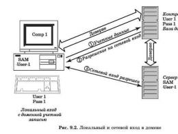
Television antenna triple square dmv. A simple homemade antenna for receiving terrestrial digital television
The gain of this antenna reaches 14 dB, which corresponds to a 5-fold increase in the signal voltage at its output compared to a half-wave vibrator. The antenna contains three square frames, of which the director and reflex are closed, and the vibrator at points a-a "(power points) is open. The frames are located symmetrically, so that their centers are on a horizontal line coinciding with the direction to the television center. The frames perform from copper or brass wire with a diameter of 3 ... 5 mm, which, with the dimensions of the decimeter range antenna, has sufficient rigidity.The dimensions of the antenna are given in the table.
The antenna frames are attached to two arrows in the middle of the horizontal sides. The top boom is made from the same material as the frames. Practice has shown that the antenna works better if the lower boom is made of insulating material, for example, getinax or textolite rod. The top boom is soldered to the frames, while the bottom boom can hold the frames in place by pouring epoxy over the connection points. The mast or stand in the indoor version of such an antenna is also made of insulating material - a getinax or textolite rod, a tube or a wooden lath. Arrows are attached to the mast or rack in the center of gravity of the antenna. The insulator is a plate of getinax, textolite or plexiglass with dimensions of 20 x 30 mm and a thickness of 2-3 mm. The ends of the vibrator frame are attached to this plate with clamps.
The input impedance of a three-element loop antenna is approximately 70 ohms, and it matches well with the characteristic impedance of a 75-ohm coaxial cable. For balancing, a quarter-wave short-circuited loop is used, made from a segment of the same cable.
The indoor antenna is carefully oriented to the image on the TV screen so that, with sufficient contrast and synchronization stability, to obtain the highest definition of the horizontal image without repetitions. In this case, it may turn out that the direction of the antenna does not coincide with the direction to the television center. The radiation pattern of a half-wave vibrator is a figure-eight in the horizontal plane with zero reception in directions coinciding with the plane in which the vibrator is located. The pattern is quite wide, and rotating the antenna up to 30° to either side of the main direction has little effect on the received signal level, but may affect the image quality. The three-element loop antenna has a narrow radiation pattern and therefore must be carefully oriented.
Loop Antennas
An ordinary loop vibrator can be transformed into a square frame, the perimeter of which is approximately equal to the wavelength (Fig. 1).

Rice. 1 Transformation of the loop vibrator into a square frame.
Antennas of this type are called loop or loop antennas. For receiving television programs, two-element and three-element loop antennas are most often used, which are otherwise called “ double square” and “triple square”. These antennas are characterized by simple design, rather high gain and narrow bandwidth.
Narrowband antennas provide frequency selectivity compared to broadband antennas. Due to this, interfering signals from other television transmitters operating on channels close in frequency cannot penetrate to the input of the television receiver. This is especially important in weak signal conditions. Often there is a need to receive a weak signal from a remote transmitter in the presence of a nearby powerful transmitter of another channel. Under such conditions, the frequency selectivity of the television receiver may not be enough. In addition, an intense interfering signal, entering the first stage of the receiver (or antenna amplifier), leads to cross-modulation of the useful signal by the interfering signal. In subsequent cascades, it is no longer possible to get rid of this. Therefore, narrow-band antennas should be used in such cases.
A two-element loop antenna is shown in fig. 2. The frames of the antenna are square in shape, and at the corners they can have roundings of an arbitrary radius, not exceeding about 1/10 of the side of the square. The frames are made of a metal tube with a diameter of 10-20 mm for antennas of channels 1-5 or 8-15 mm for antennas of channels 6-12. Metal can be any, but copper, brass or aluminum is preferable.

Rice. 2. Two-element loop antenna.
For the decimeter range, the frames are made of a copper or brass rod with a diameter of 3-6 mm. The upper arrow connects the middle of both frames, and the lower one is isolated from the vibrator frame and is attached to a plate made of textolite or organic glass. The ends of the vibrator frame are attached to the same plate with screws and nuts, for which its ends can be flattened. Arrows can be made of metal or insulating material. In the latter case, there is no need to specifically connect the frames to each other. The mast must be wooden, at least its upper part. The metal part of the mast should end 1.5 m below the antenna. The antenna frames are positioned relative to each other so that their geometric centers are on a horizontal straight line directed to the transmitter.
The cable is connected to the ends of the vibrator frame using a quarter-wave short-circuited balancing loop, which is made from the same cable. The loop and cable must approach the antenna vertically from below, the distance between them must be constant along the entire length of the loop, for which textolite spacers can be used. It is also possible to fasten the cable and the cable to the insulating plate to which the lower boom and the ends of the vibrator frame are attached. At the same time, small holes are drilled in the plate, and the cable and cable are tied to it with a nylon fishing line. The use of metal fasteners is undesirable.
To ensure rigidity, a train can be made of two metal tubes connected by their upper ends to the ends of the vibrator frame. In this case, the cable is passed inside the right tube from the bottom up, the cable braid is soldered to the right, and the central core to the left ends of the vibrator frame. The loop tubes in the lower part are closed with a jumper, by moving which you can adjust the antenna to the maximum received signal.
The dimensions of two-element loop antennas recommended for meter television channels are shown in Table 1.
Table 1. Dimensions of two-element loop antennas of meter waves, mm
Rooms channels |
||||||||||||
B \u003d 0.26L, P \u003d 0.31L, A \u003d 0.18L, where L - the average wavelength of the received frequency channel, which is given . The length of the loop for this antenna is taken from table 1(parameter W).
The dimensions of two-element loop antennas for decimeter waves are given in Table 2. Since in this range the antenna bandwidth covers several frequency channels at once, the dimensions are given not for one channel, but for a group of adjacent frequency channels.
The double-square loop antenna has a higher gain (by about 1.5 dB) compared to the two-element wave channel antenna. This applies to antennas having the same length. Antenna gain is largely determined by the distance between antenna elements. The optimal distances from this point of view are within 0.12 .... 0.15L.
Table 2. Dimensions of two-element loop antennas of decimeter waves, mm
| Channels | V | R | A | W |
| 21- 26 | 158 | 170 | 91 | 152 |
| 27-32 | 144 | 155 | 83 | 139 |
| 33-40 | 131 | 141 | 75 | 126 |
| 41-49 | 117 | 126 | 68 | 113 |
| 50-60 | 105 | 113 | 60 | 101 |
The design of a three-element loop antenna “triple square” is shown in fig. 3.

Rice. 3. Antenna "triple square".
The antenna contains three square frames, the director and reflector frames are closed, and the vibrator frame at points a - a "is open. The frames are located symmetrically, so that their centers are on a horizontal straight line directed to the television center, and are attached to two arrows in the middle of the horizontal The upper boom is made of the same material as the frames Experience has shown that the antenna works better if the lower boom is made of insulating material (for example, PCB rod) The upper boom is soldered to the frames, and the lower boom can be attached to the frames with the connection points are filled with epoxy resin.The antenna is attached to a mast made of insulating material.As in the case of the "double square", a quarter-wave short-circuited stub is used for balancing, made from a piece of the same cable.
There is also a simple design of a three-element UHF loop antenna from one piece of thick wire, shown in fig. 4.
At points A, B and C, the wires must be soldered. Instead of a stub made from a piece of coaxial cable, a quarter-wave short-circuited bridge of the same length as the stub is used. The distance between the wires of the bridge remains the same - 30 mm. The design of such an antenna is quite rigid and there is no need for a lower boom. The cable is tied to the right wire of the bridge with

Rice. 4. Antenna option “triple square”.
outside side. When the cable approaches the vibrator frame, its braid is soldered to point a, the central core to point b. The left wire of the bridge is fixed on the mast. It is only necessary to pay attention to the fact that neither the cable nor the mast is located in the space between the wires of the bridge. You can also get acquainted with the description of the design of a three-element antenna from one piece of wire. , with the design six-element - .
The input impedance of the antenna, as well as its gain, is also determined by the distance between the antenna elements. Figure 5 shows the dependences of the gain and input resistance on the distance between its elements.
For example, with a distance between the reflector and the vibrator of 0.11L, we obtain that the input impedance of the antenna is 65 Ohm, and the gain


Rice. 1.5. Dependences of the gain and input impedance of the loop antennas on the distance between the elements (top figure: 1 - “triple square”, 2 - “double square”; bottom figure: 1 - single antenna of the “square” type, 2 - “double square”, 3 - distance S = 0.11L corresponds to the maximum gain).
compared to a half-wave dipole is 5.5 dB (for a “double square”) and 6.6 dB (for a “triple square”). It should be noted that the gain values of loop antennas given in the popular literature are greatly overestimated and reach 14 dB.
Two-element and three-element loop antennas have a rather narrow main beam and therefore must be carefully oriented.
The antenna is tuned by changing the length of the cable connected to the reflector. The most optimal reflector length is 4% longer than the vibrator length.
When calculating an antenna of the “triple square” type, you can use the following formulas: B = 0.255L; P \u003d 0.261L; D \u003d 0.247L, where L is the wavelength. The optimal distance between the elements A \u003d 0.11 .... 0.15L.
Studies have shown that switching from a two-element "square" antenna containing a vibrator and a reflector to a three-element antenna leads to a gain in gain of 1.7 dB. A similar procedure for a wave channel antenna gives a gain of 2.7 dB. It should also be noted that the triple square antenna has a narrower bandwidth than the double square antenna. The dimensions of the “triple square” antennas for the meter and decimeter wave bands are given in tables 3 and 4.
For sufficient strength, the frames and the upper boom of the meter-wave antenna are made of a tube with a diameter of 10 ... 15 mm, and the distance between the ends of the vibrator frame is increased to 50 mm.
Table 3. Dimensions of three-element loop antennas of meter waves, mm
Channel numbers |
||||||||||||
EXTERNAL UHF ANTENNA OF INCREASED EFFICIENCY
The quality of television reception depends on many factors. In the conditions of the city, the interaction of the main wave of the television signal and the reflected waves is negligible. With direct visibility between the receiving antenna and the transmitting antenna, the main wave and the waves reflected from the ground, squares, streets, roofs of buildings come to the receiving point. For radio waves, a large modern city is, figuratively speaking, a heap of “mirrors” and “screens”, which are bridges, factory pipes, high-voltage lines. High-rise buildings, like a passive repeater, re-radiate waves from the transmitting antenna. The nature of the propagation of radio waves is very complex, even near the transmitter. In the radio shadow of obstacles, a weakened useful signal is received, reflected signals, noise and interference become more noticeable. In wet walls of houses, in wet trees, the signal is weakened more strongly. The maximum attenuation of the signal received by an antenna located in the radio shade of trees occurs in summer. The addition and subtraction of the main and reflected radio waves leads to the amplification of some television signals and the attenuation of others.Loop antennas in these conditions give nice results due to the attenuation of reception in the lateral and reverse directions, they are less susceptible to electrical interference and, in particular, interference from the ignition of internal combustion engines.
For long-range television reception, the most stable image is provided by loop antennas, one of which is described in this article.
Antenna parameters
Frequency range of received signals, MHz……530 – 780
Main received TV channel ….38
The range of received television channels ... 30 - 57
Polarization of received signals………horizontal
From a wide variety of loop antennas for the range DMV often make an antenna "triple square". What if the gain of the triple square is not enough, and other antenna designs are not suitable for the range of television channels of interest? At the same time, there is absolutely no place to get a sufficient number of aluminum tubes of the required diameter and specific fasteners, there is no way to assemble and install an antenna, the dimensions of which are measured in meters. Can an antenna amplifier be used, which will amplify the main wave of the TV signal along with the reflected waves received by the antenna? The solution to this problem was the combination of four triple squares into an antenna system - a phased array. The antenna gain far exceeds one triple square, and the dimensions are quite acceptable. The dimensions of the construction of one of the four triple squares are shown in the figure.

For the manufacture of a triple square, galvanized steel wire with a diameter of 3 mm is required. Galvanized is a wire that has a tin coating. Such wire is easier to solder and does not rust in the open air. It takes 2 meters of wire to make one triple square. The piece of wire must not have sharp bends, dents, scratches, rust or other defects. Before manufacturing the antenna, the wire blank is thoroughly wiped with a solvent. The wire is bent according to a pattern showing the construction of a triple square. The wire joints at the top of the squares are soldered. The sections of the wire at the joints are covered with a flux prepared from hydrochloric acid by etching with zinc. With a soldering iron with a power of forty watts, and preferably sixty watts, the sections are covered with fusible solder, as far as the power of the soldering iron allows. Then the joints are pulled together with one or two turns of tinned copper wire with a diameter of 0.6-1 mm and soldered again. Finally, the joints are well soldered over the gas stove burnerusing solder and rosin. The remaining rosin is removed from the resulting structure and washed off with a solvent. The solder joint should be well tinned, providing reliable contact and mechanical strength. Triple squares must not be painted or varnished.
Before combining the triple squares into a phased array, each one needs to be checked and adjusted. Checking and adjustment is carried out indoors. A television coaxial cable with a characteristic impedance of 75 ohms is connected to the triple square, as shown in the figure. The image on the TV screen when setting up the antenna in the room may be black and white with a lot of noise. Triple square adjustment is performed based on the least amount of noise on the TV screen. If one triple square does not give a color image, it does not matter, when combined into a phased array, the image quality will increase significantly. Having connected the triple square to the antenna input of the TV, it is necessary to find the point of soldering the cable to the lower vertical part of the antenna structure by moving the connection point vertically. When moving the connection, the center core of the cable and the cable screen must be connected at the same level. In one copy of the triple square best picture on the TV screen can be obtained by soldering the cable almost at the closing horizontal section at the very bottom of the antenna, in other copies as shown in the figure in the third copies in the middle. Each triple square has its own optimal cable connection point. After finishing the setup and checking the triple squares, it is important not to mix up the cable connection points. To obtain a good quality of the antenna, 6-8 triple squares should be made, from which four giving the best results should be selected.
Triple squares, which are elements of a phased array, are connected by a coaxial cable. The basis of the antenna design is a wooden frame. The length of the vertical cable segments connecting two triple squares is selected experimentally. It is impossible to accurately determine the length of the cable segments in advance due to differences in the parameters of different types of cable and the unpredictable properties of the triple squares made.
Two triple squares are fixed by wrapping a PVC tube on one vertical frame element, which is a wooden block. In turn, identical pieces of cable 220, 240, 260.280, 300 millimeters each are connected to the triple squares. The opposite ends of the cable segments are connected to the screen-screen and core-core and connected to the cable going to the antenna input of the TV. By best quality image, the length of the vertical cable segments connecting the two triple squares is selected. The main contributor to the tuning is the length of the cable segments compared to the distance between the triple squares. When setting up, you can reduce or increase the distance between the triple squares, but this will not give much effect, so the distances in the design drawing between the triple squares are not given. The image on the TV screen should be better than when received on one triple square.
The frame is temporarily assembled from four wooden bars fastened together with a rope. Four triple squares are installed on the frame, connected by vertical cable segments. The length of two identical horizontal cable segments connecting the vertical segments with the cable laid to the TV antenna input is specified experimentally. For the final adjustment, two identical horizontal segments with a length of 130, 150, 170 or 190 millimeters are alternately soldered.
For the final manufacture of the frame, four wooden bars 8-11 millimeters thick, 60-70 millimeters wide, 520 millimeters long and three wooden bars of the same thickness and width 490 millimeters long will be required. The ends of the bars are coated with epoxy resin and dried for five days, then the entire surface of the bars is coated with epoxy resin and dried for five days. After coating with epoxy resin, wooden bars are painted with nitro paint at least twice. Before installing triple squares and cable segments that combine triple squares into a phased array, the first part of the frame is assembled from two vertical and two horizontal bars. The contacting surfaces of the bars are coated with epoxy resin, connected with screws and dried for at least three days. After the epoxy resin dries, the two screws connecting the upper horizontal bar with the vertical bars are unscrewed. Four screws securing the central horizontal bar remain.
Triple squares are installed on a wooden frame, connected by pieces of a coaxial cable. Triple squares are attached to the frame with several turns of PVC tubing. A cable is soldered to the antenna, going to the TV of the required length.
For correct phasing of the antenna system, the center conductors and screens of the coaxial cable segments are connected to triple squares in accordance with the phasing scheme. The end of the cable connected to the antenna is enclosed in a PVC tube with a diameter of 10-12 millimeters and a length of about three meters for protection antenna cable from weather influences. The PVC tube and cable are fixed with a thread on a horizontal bar. The soldering of the screen and the central core of the cable segments are isolated from each other with electrical tape. On top of the installed triple squares and cables, two vertical bars are installed, on top of them in the center is one horizontal one. The frame parts are connected with screws with a diameter of 6 millimeters. When installing the screws, the holes left after unscrewing the screws connecting the upper horizontal bar with the vertical bars are used. Coaxial cable segments and parts of triple squares are enclosed within a wooden structure that reliably protects the solder points from the weather.
The gaps between the bars from the sides and ends are sealed using building sealant "liquid nails".
The antenna is mounted on the mast using clamps corresponding to the diameter of the pipe. Screws pass through the holes in the horizontal bars. The antenna is fixed at two points. By loosening the clamp screws, you can precisely orient the antenna to the transmitter.
Galvanized wire, pipe clamp, epoxy, paint can be purchased at a building materials store. Coaxial tv cable with a wave impedance of 75 ohms should be selected with a central core of copper and double screen consisting of a foil and a braid of copper wires. Best Results can be obtained by using the largest diameter cable with as many cores as possible in a screen braid.
The distances between the elements of the phased array, the dimensions of the triple square and the length of the cable segments are chosen through numerous experiments, in order to ensure reception is possible more TV channels and at the same time the smallest possible dimensions, reducing the mass of the antenna and facilitating installation. Reception on the antenna is possible through an obstacle from closely spaced trees. The antenna has a low windage. Due to the location of the cables inside the wooden sealed frame, a long service life and protection from the influence of weather factors are ensured. The quality of the received image does not depend on the time of year and time of day.
Denisov Platon Konstantinovich, Simferopol
Download: HIGH PERFORMANCE UHF OUTDOOR ANTENNA Triple Square
If "broken" links are found, you can leave a comment and the links will be restored as soon as possible.
Buying a good antenna for the country is not always advisable. Especially if it is visited from time to time. It's not so much the cost, but the fact that after a while it may not be in place. Therefore, many people prefer to make an antenna for giving their own. The cost is minimal and the quality is good. And the most important point- A do-it-yourself TV antenna can be made in half an hour or an hour and then, if necessary, easily repeated ...
Digital television in DVB-T2 format is transmitted in the UHF range, and there is either a digital signal or it is not. If the signal is received, then the picture is of good quality. Concerning. for reception digital television suitable for any decimeter antenna. Many radio amateurs are familiar with the TV antenna, which is called "zigzag" or "eight". This do-it-yourself TV antenna is assembled in just a matter of minutes.
To reduce the amount of interference, a reflector is placed behind the antenna. The distance between the antenna and the reflector is selected experimentally - according to the "purity" of the picture  You can attach foil to the glass and get a good signal ....
  Copper tube or wire is the best option, it bends well, it is easy to
Making it is very simple, the material is any conductive metal: tube, rod, wire, strip, corner. She accepts, despite the simplicity, well. It looks like two squares (rhombuses) connected to each other. In the original, a reflector is located behind the square - for more confident signal reception. But it is more needed for analog signals. To receive digital television, it is quite possible to do without it or install it later if the reception is too weak.
materials
Optimum for this homemade television antenna, copper or aluminum wire with a diameter of 2-5 mm is suitable. In this case, everything can be done in just an hour. You can also use a tube, a corner, a strip of copper or aluminum, but you will need some kind of device to bend the frame desired shape. The wire can be bent with a hammer, fixing it in a vise.

You will also need a coaxial antenna cable of the required length, a plug suitable for the connector on your TV, some kind of mount for the antenna itself. The cable can be taken with a resistance of 75 ohms and 50 ohms (the second option is worse). If you make a TV antenna with your own hands for installation on the street, pay attention to the quality of the insulation.
Mounting depends on where you are going to hang a homemade antenna for digital television. On the upper floors, you can try to use it as a home and hang it on curtains. Then you need large pins. In the country or if you take out homemade TV antenna on the roof, it will be necessary to fasten it to a pole. For this case, look for suitable clamps. To work, you will also need a soldering iron, sandpaper and / or a file, a needle file.
Do you need a calculation
To receive a digital signal, there is no need to count the wavelength. It is simply desirable to make the antenna more broadband - in order to receive as many signals as possible. To do this, some changes have been made to the original design (pictured above) (further in the text).
You can do the calculation if you want. To do this, you need to find out on which wave the signal is broadcast, divide by 4 and get the required side of the square. To get the required distance between the two parts of the antenna, make the outer sides of the diamonds a little longer, the inner ones shorter.

Drawing of the G8 antenna for receiving digital TV
- The length of the "inner" side of the rectangle (B2) is 13 cm,
- "outer" (B1) - 14 cm.
Due to the difference in lengths, the distance between the squares is formed (they should not be connected). The two extreme sections are made 1 cm longer - so that you can roll the loop to which the coaxial antenna cable is soldered.
Frame making
If you count all the lengths, you get 112 cm. We cut off the wire or the material that you have, take the pliers and the ruler, and begin to bend. The angles should be at 90° or so. With the lengths of the sides, you can make a little mistake - this is not fatal. It turns out like this:
- The first section is 13 cm + 1 cm per loop. The loop can be bent immediately.
- Two sections of 14 cm.
- Two 13 cm each, but with a turn in the opposite direction - this is the place of the inflection to the second square.
- Again two 14 cm.
- The last one is 13 cm + 1 cm per loop.
Actually the antenna frame is ready. If everything was done correctly, a distance of 1.5-2 cm was obtained between the two halves in the middle. There may be slight discrepancies. Next, we clean the loops and the place of the inflection to bare metal (treat with fine-grained emery), tin. Connect two loops, compress with pliers to hold tight.

Cable preparation
We take the antenna cable, carefully clean it. How to do this is shown in step by step photo. Strip the cable on both sides. One end will be attached to the antenna. Here we clean it so that the wire sticks out 2 cm. If it turned out more, the excess (later) can be cut off. Twist the screen (foil) and braid into a bundle. It turned out two conductors. One is the central monocore of the cable, the second is twisted from a multitude of braid wires. Both are needed and need to be tinned.

Solder the plug to the second edge. There is enough length of 1 cm or so. Also form two conductors, tin.
The plug in those places where we will carry out soldering, wipe it with alcohol or a solvent, clean it with emery (you can use a needle file). Put the plastic part of the plug on the cable, now you can start soldering. We solder a monocore to the central outlet of the plug, and a stranded twist to the side outlet. The last thing is to crimp the grip around the insulation.

Then you can simply wind the plastic tip, you can fill it with glue or non-conductive sealant (this is important). While the glue / sealant has not hardened, we quickly assemble the plug (we wind the plastic part), remove the excess composition. So the plug will be almost eternal.
DIY DVB-T2 TV antenna: assembly
Now it remains to connect the cable and frame. Since we were not tied to a specific channel, we will solder the cable to the midpoint. This will increase the bandwidth of the antenna - more channels will be received. Therefore, we solder the second cut end of the cable to the two sides in the middle (those that were stripped and tinned). Another difference from the “original version” is that the cable does not need to be looped around the frame and soldered at the bottom. This will also expand the reception range.
The assembled antenna can be checked. If the reception is normal, you can finish the assembly - fill the soldering points with sealant. If the reception is bad, try to find a place where you can catch better first. If there are no positive changes, you can try replacing the cable. For ease of experiment, you can use ordinary telephone noodles. She's worth every penny. Solder the plug and the frame to it. Try with her. If it "catches" better, it's a bad cable. In principle, you can work on "noodles", but not for long - it will quickly become unusable. It is better, of course, to put a normal antenna cable.

To protect the junction of the cable and the antenna frame from atmospheric influences, the soldering points can be wrapped with ordinary electrical tape. But this is not a reliable way. If you remember, you can put on a few heat shrink tubes before soldering to insulate with their help. But the most reliable way- fill everything with glue or sealant (they should not conduct current). As a "case" you can use covers for 5-6 liter water bottles, ordinary plastic covers for cans, etc. We make recesses in the right places - so that the frame “lays down” in them, do not forget about the cable outlet. Fill with sealing compound, wait until it seizes. Everything, a do-it-yourself TV antenna for receiving digital television is ready.
Homemade antenna double and triple square
This is a narrowband antenna, which is used when you need to receive a weak signal. It can even help if a weaker signal is "clogged" by a stronger one. The only drawback is that you need an exact orientation to the source. The same design can be done to receive digital television.
 You can make five frames - for a more confident reception
  It is undesirable to paint or varnish - reception worsens. This is possible only in close proximity to the transmitter.
The advantages of this design are that the reception will be confident even at a considerable distance from the repeater. Only it will be necessary to specifically find out the frequency of broadcasting, to withstand the dimensions of the frames and the matching device.
Construction and materials
Make it from tubes or wire:
- 1-5 TV channel of the MV range - tubes (copper, brass, aluminum) with a diameter of 10-20 mm;
- 6-12 TV channel of the MV range - tubes (copper, brass, aluminum) 8-15 mm;
- UHF range - copper or brass wire with a diameter of 3-6 mm.
The double square antenna consists of two frames connected by two arrows - upper and lower. The smaller frame is a vibrator, the larger one is a reflector. An antenna consisting of three frames gives a greater gain. The third, smallest, square is called the director.

The upper arrow connects the middle of the frames, it can be made of metal. The lower one is made of insulating material (textolite, gettinax, wooden plank). Frames should be installed so that their centers (crossing points of the diagonals) are on the same straight line. And this line should be directed to the transmitter.
The active frame - the vibrator - has an open circuit. Its ends are screwed to a textolite plate measuring 30 * 60 mm. If frames are made from a tube, the edges are flattened, holes are made in them and the lower arrow is attached through them.
The mast for this antenna must be wooden. In any case, the upper part of it. Moreover, the wooden part should begin at a distance of at least 1.5 meters from the level of the antenna frames.
Dimensions
All dimensions for the manufacture of this TV antenna with your own hands are shown in the tables. The first table is for the meter range, the second is for the decimeter range.

In three-frame antennas, the distance between the ends of the vibrator (middle) frame is made larger - 50 mm. Other dimensions are given in the tables.

Connecting an active frame (vibrator) via a short-circuited loop
Since the frame is a symmetrical device, and it must be connected to an unbalanced coaxial antenna cable, it is necessary matching device. In this case, a balancing short-circuited loop is usually used. It is made from pieces of antenna cable. The right segment is called the “loop”, the left one is called the “feeder”. A cable is attached to the junction of the feeder and the cable, which goes to the TV. The length of the segments is selected based on the wavelength of the received signal (see table).

A short piece of wire (loop) is cut at one end by removing the aluminum screen and twisting the braid into a tight bundle. Its center conductor can be cut to insulation, as it does not matter. Divide and feeder. Here, too, the aluminum screen is removed and the braid is twisted into a bundle, but the central conductor remains.
Further assembly goes like this:
- The braid of the loop and the central conductor of the feeder are soldered to the left end of the active frame (vibrator).
- The feeder braid is soldered to the right end of the vibrator.
- The lower end of the loop (braid) is connected to the feeder braid using a rigid metal jumper (you can use a wire, just make sure that it makes good contact with the braid). In addition to the electrical connection, it also sets the distance between the sections of the matching device. Instead of a metal jumper, you can twist the braid of the lower part of the cable into a bundle (remove the insulation in this area, remove the screen, roll it into a bundle). To provide good contact solder the bundles together with low-melting solder.
- The pieces of cable must be parallel. The distance between them is about 50 mm (some deviations are possible). To fix the distance, clamps made of a dielectric material are used. You can also attach a matching device to a textolite plate, for example.
- The cable going to the TV is soldered to the bottom of the feeder. The braid is connected to the braid, the center conductor is connected to the center conductor. To reduce the number of connections, the feeder and cable to the TV can be made one. Only in the place where the feeder should end should the insulation be removed so that a jumper can be installed.
This matching device allows you to get rid of interference, a blurry contour, a second blurred image. It is especially useful at a great distance from the transmitter, when the signal will be clogged with interference.
Another variant of the triple square
In order not to connect a short-circuited loop, the triple square antenna vibrator is made elongated. In this case, you can connect the cable directly to the frame as shown in the figure. Only the height at which the antenna wire is soldered is determined in each case individually. After the antenna is assembled, “tests” are carried out. The cable is connected to the TV, the center conductor and the braid are moved up / down, achieving a better picture. In the position where the picture will be most clear, the antenna cable taps are soldered, the soldering points are isolated. The position can be any - from the bottom jumper to the transition to the frame.

Sometimes one antenna does not give the desired effect. The signal turns out to be a weak image - black and white. In this case, the standard solution is to install a TV signal amplifier.
The simplest antenna for giving - from metal cans
For the manufacture of this television antenna in addition to the cable, you will only need two aluminum or tin cans and a piece of wooden plank or plastic pipe. Banks must be metal. You can take beer aluminum, you can - tin. The main condition is that the walls are even (not ribbed).

Banks are washed and dried. The end of the coaxial wire is cut - by twisting the strands of the braid and cleaning the central core from insulation, two conductors are obtained. They are attached to banks. If you know how, you can solder. No - take two small self-tapping screws with flat caps (you can use “fleas” for drywall), twist a loop at the ends of the conductors, thread a self-tapping screw with a washer installed on it, screw it to the jar. Just before that, you need to clean the metal of the can - removing the plaque with fine-grained sandpaper.

Banks are fixed on the bar. The distance between them is selected individually - according to the best picture. You should not hope for a miracle - there will be one or two channels in normal quality, or maybe not ... It depends on the position of the repeater, the "cleanliness" of the corridor, how correctly the antenna is oriented ... But as an exit in an emergency - this is a great option.
A simple Wi-Fi antenna from a metal can
Antenna for receiving wifi signal can also be made from improvised means - from a tin can. This do-it-yourself TV antenna can be assembled in half an hour. This is if everything is done slowly. The jar should be made of metal, with smooth walls. Tall and narrow cans are great. If you put a homemade antenna on the street, find a jar with a plastic lid (as in the photo). The cable is taken antenna, coaxial, with a resistance of 75 ohms.

In addition to the can and cable, you will also need:
- radio frequency connector RF-N;
- a piece of copper or brass wire 2 mm in diameter and 40 mm long;
- cable with a socket suitable for a Wi-Fi card or adapter.
The Wi-Fi transmitters operate on the 2.4 GHz frequency with a wavelength of 124 mm. So, it is advisable to choose a jar such that its height is at least 3/4 of the wavelength. For this case, it is better that it be more than 93 mm. The diameter of the jar should be as close as possible to half the wavelength - 62 mm for a given channel. There may be some deviations, but the closer to the ideal, the better.
Dimensions and Assembly
When assembling, a hole is made in the bank. It must be placed exactly at the right point. Then the signal will be amplified several times. It depends on the diameter of the selected can. All parameters are given in the table. Measure exactly the diameter of your jar, find the right line, have all the right sizes.

| D - diameter | Lower limit of attenuation | Upper damping limit | LG | 1/4 LG | 3/4 LG |
|---|---|---|---|---|---|
| 73 mm | 2407.236 | 3144.522 | 752.281 | 188.070 | 564.211 |
| 74 mm | 2374.706 | 3102.028 | 534.688 | 133.672 | 401.016 |
| 75 mm | 2343.043 | 3060.668 | 440.231 | 110.057 | 330.173 |
| 76 mm | 2312.214 | 3020.396 | 384.708 | 96.177 | 288.531 |
| 77 mm | 2282.185 | 2981.170 | 347.276 | 86.819 | 260.457 |
| 78 mm | 2252.926 | 2942.950 | 319.958 | 79.989 | 239.968 |
| 79 mm | 2224.408 | 2905.697 | 298.955 | 74.738 | 224.216 |
| 80 mm | 2196.603 | 2869.376 | 282.204 | 070.551 | 211.653 |
| 81 mm | 2169.485 | 2833.952 | 268.471 | 67.117 | 201.353 |
| 82 mm | 2143.027 | 2799.391 | 256.972 | 64.243 | 192.729 |
| 83 mm | 2117.208 | 2765.664 | 247.178 | 61.794 | 185.383 |
| 84 mm | 2092.003 | 2732.739 | 238.719 | 59.679 | 179.039 |
| 85 mm | 2067.391 | 2700.589 | 231.329 | 57.832 | 173.497 |
| 86 mm | 2043.352 | 2669.187 | 224.810 | 56.202 | 168.607 |
| 87 mm | 2019.865 | 2638.507 | 219.010 | 54.752 | 164.258 |
| 88 mm | 1996.912 | 2608.524 | 213.813 | 53.453 | 160.360 |
| 89 mm | 1974.475 | 2579.214 | 209.126 | 52.281 | 156.845 |
| 90 mm | 1952.536 | 2550.556 | 204.876 | 51.219 | 153.657 |
| 91 mm | 1931.080 | 2522.528 | 201.002 | 50.250 | 150.751 |
| 92 mm | 1910.090 | 2495.110 | 197.456 | 49.364 | 148.092 |
| 93 mm | 1889.551 | 2468.280 | 194.196 | 48.549 | 145.647 |
| 94 mm | 1869.449 | 2442.022 | 191.188 | 47.797 | 143.391 |
| 95 mm | 1849.771 | 2416.317 | 188.405 | 47.101 | 141.304 |
| 96 mm | 1830.502 | 2391.147 | 185.821 | 46.455 | 139.365 |
| 97 mm | 1811.631 | 2366.496 | 183.415 | 45.853 | 137.561 |
| 98 mm | 1793.145 | 2342.348 | 181.169 | 45.292 | 135.877 |
| 99 mm | 1775.033 | 2318.688 | 179.068 | 44.767 | 134.301 |
The procedure is as follows:

You can do without an RF connector, but with it everything is much simpler - it is easier to set the emitter vertically upwards, connect the cable that goes to the router (router) or Wi-Fi card.
Digital television broadcasts in the decimeter wave range. Therefore, you can use almost any UHF antenna. But I needed simple, easily repeatable and strong UHF antenna range.
Such that it could be carried with you, and on occasion it was not a pity to give it to people for a small amount.
Based on the well-known eight“, with the difference that I used it without a reflector.
The material for the antenna web can be taken from any conductive, suitable section. It can be copper or aluminum wire with a thickness of 1 to 5 mm, a tube, a strip, a tire, a corner, a profile ... I took a copper wire with a diameter of 3 mm. Easy to solder, easy to bend when assembling, easy to align if bent.
The outer side of the square is 14 cm, the inner side is slightly less - 13 cm due to the fact that the middle of the two squares does not converge, about 2 cm from corner to corner.
So, if you are not making an antenna out of wire, then you measure it - the upper sides are 14 cm each, the sides are 13 cm each.
All sizes are approx. Don't be afraid to miscalculate or make a mistake. Our plans do not include the production of an antenna that meets all standards. We need a simple but workhorse. Surrogate, but reliable. Surrogate because:
1
. Personally, I couldn't stand the dimensions.
2
. The reflector is missing.
3
. I took the cable 50 ohms instead of 75 ohms, but with a thick braid. Friends usually used such a cable for car antennas for radio stations 27 MHz.
Nevertheless, the antenna works and is very good.
A digital signal has a feature, it either exists or it doesn't. When receiving analog television, different channels were shown with different levels of interference, and when removed, the snow level on the screen simply increased until the signal completely disappeared. In digital, the signal is almost the same on all channels, and if there is reception, then there are all channels.
I have tested this antenna on more than a dozen TVs in our region.
So. We measure a piece with a total length of 112 cm and bend the wire. The first section is 13 cm + 1 cm for the loop (for strength). The second and third - 14 cm each, the fourth and heels - 13 cm each, the sixth and seventh - 14 cm each, and the last eighth - 13 cm + 1 cm stiffening loop.
At the two ends, we clean 1.5 - 2 cm each, twist two loops for each other, and then solder the junction. This will be one cable connection pin. After 2 cm another. Where to solder the central core, where the braid is, does not matter.

Distance between solder joints 2cm
I took a cable about three meters. In most cases, it is enough if you are not doing it for yourself personally. Measure out as much as you need.
The cable was stripped from the side of the antenna by two centimeters, to the plug - 1 cm. If the plug is the same as in the photo. You can take any, stronger.

cable stripping
The plug was cleaned with a needle file and a scalpel.

After sealing, both soldering points are filled with glue from a gun. On the plug, first, hot glue is poured into the place of soldering and into a plastic cap, with a margin, the excess can then be removed. Then, while the glue has not cooled down, everything is quickly assembled. You can't gnaw through such a joint with your teeth. Reliable and flexible at the same time.
The soldering on the antenna itself is also filled with glue, but for the rigidity of the structure, a frame is taken - any cover, box, .... I took the cap from a 20 liter water bottle, of which I have accumulated a sufficient amount. If you are making an antenna, like me, for mass production, then it is better to use materials that are common, literally lying under your feet for better antenna repeatability. If the antenna is made in a single copy for quick riveting, then you can not fill anything at all.

It turned out such a design that can be stuck anywhere - on a cornice, on a curtain, on a window frame. To do this, you can carry a piece of wire, a couple of screws, a couple of pins ...

Antenna assembly
If the antenna is wrinkled during transfer, it is easily and without damage aligned. This is perhaps its most important plus.
I do not always carry such a design with me, but only when I receive a specific order for connecting a DVB-T2 digital television tuner. It fits easily with the tool in my backpack.
It is more convenient to make several antennas at once. Takes less time.
This is how my friend fixed the antenna, using it as an external one. The tower is about 9 km. Reception is confident despite the simplicity of the antenna.

EXTERNAL UHF ANTENNA OF INCREASED EFFICIENCY
The quality of television reception depends on many factors. In the conditions of the city, the interaction of the main wave of the television signal and the reflected waves is inevitable. With direct visibility between the receiving antenna and the transmitting antenna, the main wave and the waves reflected from the ground, squares, streets, roofs of buildings come to the receiving point.
For radio waves, a large modern city is, figuratively speaking, a heap of “mirrors” and “screens”, which are bridges, factory pipes, high-voltage lines. High-rise buildings, like a passive repeater, re-radiate waves from the transmitting antenna. The nature of the propagation of radio waves is very complex, even near the transmitter. In the radio shadow of obstacles, a weakened useful signal is received, reflected signals, noise and interference become more noticeable. In wet walls of houses, in wet trees, the signal is weakened more strongly. The maximum attenuation of the signal received by an antenna located in the radio shade of trees occurs in summer. The addition and subtraction of the main and reflected radio waves leads to the amplification of some television signals and the attenuation of others.
Loop antennas perform well under these conditions due to the attenuation of reception in the lateral and reverse directions, they are less affected by electrical interference and, in particular, interference from the ignition of internal combustion engines.
For long-range television reception, the most stable image is provided by loop antennas, one of which is described in this article.
Antenna parameters
Frequency range of received signals, MHz……530 – 780
Main received TV channel ….38
The range of received television channels ... 30 - 57
Polarization of received signals………horizontal
From a wide variety of loop antennas for the range DMV often make an antenna "triple square". What if the gain of the triple square is not enough, and other antenna designs are not suitable for the range of television channels of interest? At the same time, there is absolutely no place to get a sufficient number of aluminum tubes of the required diameter and specific fasteners, there is no way to assemble and install an antenna, the dimensions of which are measured in meters. Can apply antenna amplifier, which will amplify the main wave of the TV signal along with the reflected waves received by the antenna? The solution to this problem was the combination of four triple squares into an antenna system - a phased array. The antenna gain far exceeds one triple square, and the dimensions are quite acceptable. The dimensions of the construction of one of the four triple squares are shown in the figure.

For the manufacture of a triple square, galvanized steel wire with a diameter of 3 mm is required. Galvanized is a wire that has a tin coating. Such wire is easier to solder and does not rust in the open air. It takes 2 meters of wire to make one triple square. The piece of wire must not have sharp bends, dents, scratches, rust or other defects. Before manufacturing the antenna, the wire blank is thoroughly wiped with a solvent. The wire is bent according to a pattern showing the construction of a triple square. The wire joints at the top of the squares are soldered. The sections of the wire at the joints are covered with a flux prepared from hydrochloric acid by etching with zinc. With a soldering iron with a power of forty watts, and preferably sixty watts, the sections are covered with fusible solder, as far as the power of the soldering iron allows. Then the joints are pulled together with one or two turns of tinned copper wire with a diameter of 0.6-1 mm and soldered again. Finally, the joints are well soldered over the gas stove burner using solder and rosin. The remaining rosin is removed from the resulting structure and washed off with a solvent. The solder joint should be well tinned, providing reliable contact and mechanical strength. Triple squares must not be painted or varnished.
Before combining the triple squares into a phased array, each one needs to be checked and adjusted. Checking and adjustment is carried out indoors. A television coaxial cable with a characteristic impedance of 75 ohms is connected to the triple square, as shown in the figure. The image on the TV screen when setting up the antenna in the room may be black and white with a lot of noise.
Triple square adjustment is performed based on the least amount of noise on the TV screen. If one triple square does not give a color image, it does not matter, when combined into a phased array, the image quality will increase significantly. Having connected the triple square to the antenna input of the TV, it is necessary to find the point of soldering the cable to the lower vertical part of the antenna structure by moving the connection point vertically. When moving the connection, the center core of the cable and the cable screen must be connected at the same level. In some copies of the triple square, the best image on the TV screen can be obtained by soldering the cable almost at the closing horizontal section at the very bottom of the antenna, in other copies, as shown in the figure in the third copies in the middle. Each triple square has its own optimal cable connection point. After finishing the setup and checking the triple squares, it is important not to mix up the cable connection points.
To obtain a good quality of the antenna, 6-8 triple squares should be made, from which four giving the best results should be selected.
Triple squares, which are elements of a phased array, are connected by a coaxial cable. The basis of the antenna design is a wooden frame. The length of the vertical cable segments connecting two triple squares is selected experimentally. It is impossible to accurately determine the length of the cable segments in advance due to differences in parameters various types cable and unpredictable properties of manufactured triple squares.
Two triple squares are fixed by wrapping a PVC tube on one vertical frame element, which is a wooden block. In turn, identical pieces of cable 220, 240, 260.280, 300 millimeters each are connected to the triple squares. The opposite ends of the cable segments are connected to the screen-screen and core-core and connected to the cable going to the antenna input of the TV. The length of the vertical cable segments connecting two triple squares is selected according to the best image quality. The main contributor to the tuning is the length of the cable segments compared to the distance between the triple squares. When setting up, you can reduce or increase the distance between the triple squares, but this will not give much effect, so the distances in the design drawing between the triple squares are not given. The image on the TV screen should be better than when received on one triple square.
The frame is temporarily assembled from four wooden bars fastened together with a rope. Four triple squares are installed on the frame, connected by vertical cable segments. The length of two identical horizontal cable segments connecting the vertical segments with the cable laid to the TV antenna input is specified experimentally. For the final adjustment, two identical horizontal segments with a length of 130, 150, 170 or 190 millimeters are alternately soldered.
For the final manufacture of the frame, four wooden bars 8-11 millimeters thick, 60-70 millimeters wide, 520 millimeters long and three wooden bars of the same thickness and width 490 millimeters long will be required. The ends of the bars are coated with epoxy resin and dried for five days, then the entire surface of the bars is coated with epoxy resin and dried for five days. After coating with epoxy resin, wooden bars are painted with nitro paint at least twice. Before installing triple squares and cable segments that combine triple squares into a phased array, the first part of the frame is assembled from two vertical and two horizontal bars. The contacting surfaces of the bars are coated with epoxy resin, connected with screws and dried for at least three days. After the epoxy resin dries, the two screws connecting the upper horizontal bar with the vertical bars are unscrewed. Four screws securing the central horizontal bar remain.
Triple squares are installed on a wooden frame, connected by pieces of a coaxial cable. Triple squares are attached to the frame with several turns of PVC tubing. A cable is soldered to the antenna, going to the TV of the required length.
For correct phasing of the antenna system, the center conductors and screens of the coaxial cable segments are connected to triple squares in accordance with the phasing scheme. The end of the cable connected to the antenna is enclosed in a PVC tube with a diameter of 10-12 millimeters and a length of about three meters to protect the antenna cable from the weather. The PVC tube and cable are fixed with a thread on a horizontal bar. The soldering of the screen and the central core of the cable segments are isolated from each other with electrical tape. On top of the installed triple squares and cables, two vertical bars are installed, on top of them in the center is one horizontal one.
The frame parts are connected with screws with a diameter of 6 millimeters. When installing the screws, the holes left after unscrewing the screws connecting the upper horizontal bar with the vertical bars are used. Coaxial cable segments and parts of triple squares are enclosed within a wooden structure that reliably protects the solder points from the weather.
The gaps between the bars from the sides and ends are sealed using building sealant "liquid nails".
The antenna is mounted on the mast using clamps corresponding to the diameter of the pipe. Screws pass through the holes in the horizontal bars. The antenna is fixed at two points. By loosening the clamp screws, you can precisely orient the antenna to the transmitter.
Galvanized wire, pipe clamp, epoxy, paint can be purchased at a building materials store. A coaxial television cable with a characteristic impedance of 75 ohms should be selected with a central conductor of copper and a double screen consisting of a foil and a braid of copper conductors. The best results can be obtained by using the largest diameter cable with as many strands as possible in the shield.
The distances between the elements of the phased array, the dimensions of the triple square and the length of the cable segments were chosen through numerous experiments in order to ensure the reception of the largest possible number of television channels and at the same time the smallest possible dimensions, reducing the mass of the antenna and facilitating installation. Reception on the antenna is possible through an obstacle from closely spaced trees. The antenna has a low windage. Due to the location of the cables inside the wooden sealed frame, a long service life and protection from the influence of weather factors are ensured. The quality of the received image does not depend on the time of year and time of day.
Denisov Platon Konstantinovich, Simferopol
With DVB-T2 support, and of course, he needed an antenna, which naturally needs to be made by hand. How to make an antenna for DVB-T2 with your own hands will be discussed further.
To begin with, I decided to test the Kharchenko biquadrat antenna, or simply the "eight" in common people. For manufacturing, we need a copper or aluminum wire with a diameter of 2-5 mm. I had a 2.5 square VVG at hand and I decided to try to make an antenna for DVB-T2 from it.
Antenna calculation
We will find out our frequencies of both DVB-T2 packages in our area. For this you can go to the website of the Interactive map of CETV and see which tower is closer to you, one or both packages of channels are broadcasting and at what frequencies. In our suburbs of St. Petersburg, these are 586 MHz and 666 MHz.
Now, knowing the packet frequencies, we need to calculate the length of the side of the square of our DVB-T2 antenna. It is equal to a quarter of a wavelength.
That is, for our 586MHz: 300000000/586000000=0,51 meter. Quarter wavelength respectively 0,51/4=0,127 meters or 12,7 cm.
For the second 666 MHz multiplex, we calculate similarly and get 11,2 cm.
We are interested in L1. H and B for an antenna with a reflector (grid), amplifies the signal. I did without it.
Now if we make an antenna for two DVB-T2 channel packages, we determine the average length. That is, we add our lengths and divide in half.
L1=(12.7+11.2)/2=11.95 round up to 12 cm.
Antenna assembly for DVB-T2
Everything should be clear here. We take our segment of VVG or whatever you have. To determine the approximate length of the wire needed to assemble the antenna, you can L1 * 8 and throw a couple of centimeters. 12*8+2=98 cm was needed to make my antenna.
If you have a thick wire 4-5 mm in diameter, then most likely you will not be able to do without a vice. I had enough pliers.
We clean the wire from insulation. Then bend the biquadrat with pliers. Let's see the pictures. All angles are 90 degrees.

Then solder the 75 ohm TV cable. We solder the core to one square, the braid to another.

The signal at high frequencies propagates along the surface of the conductor, so it is better to paint the antenna after assembly. I used leftover acrylic facade paint. It is better to fill the place of soldering with hot-melt adhesive or sealant.
We fasten the wire from the place of soldering with ties (straps) along the sides of the square, as in the photo. This mandatory action is antenna matching.
Testing a homemade antenna on a homemade TV
So the biquadrate gives a signal amplification of the order of 6 dB, and up to the tower 26 km in a straight line. Although the CETV website indicates that we are in the zone of a confident signal, I doubted and prepared what I had done a long time ago.
He climbed to the second floor of the house and pulled out the antenna to the scaffolding. He pointed towards the tower and turned on the TV. The TV confidently received both digital TV packages.
I brought a homemade antenna into the house, the TV continued to confidently show perfectly.

Then I dragged my homemade telly to the change house, and hung the antenna inside the change house on the door. The TV continued to receive a signal confidently.
You can also make a Kharchenko bi-square antenna for 3G, 4G or Wi-Fi, you just need to recalculate to the appropriate frequency.