Tricolor TV gs 8300m power supply. And now different nodes close-up
October 2012. Within a week they brought 15 GS-8300s with dead power supplies, including blown tracks, cracked PCB and burnt SMD resistors.

 hover your mouse over the image to enlarge it
How everything happened is clear - the electrolytic or oxide capacitor standing at the input (C5) dries out and produces pulsations, but so far everything is working. The transistor of the primary winding of the transformer (Q1) overheats, the SMD parts around it burn out, the board tracks crack and the power supply becomes faulty.
The original power supplies ran out a long time ago, but the GS-8300 receivers kept coming and going. Of course, repairs were possible by fusing tracks, installing jumpers, soldering parts - in short, it was possible to restore the power supply from the ashes and at the same time it would work properly, although the work did not look entirely aesthetically pleasing and it was better for the client not to see the result of the master’s actions. And, of course, it took a lot of time to repair each block.


Therefore, I went the other way - I took it and adapted it for the GS-8300 receiver, but I’ll just make a reservation that there are several models of power supplies for the DRE-5000, the one on the left is suitable in the photo below - it is also the most common (the right one in the image does not fit in height )

Pinout of DRE-500 and GS-8300 connectors
No. DRE-5000 GS-8300
|
30 V |
no/delete |
|
|
22 V |
24 V |
|
|
12 V |
frame |
|
|
frame |
||
|
3.3V |
3.3V |
|
|
3.3V |
3.3V |
|
|
frame |
frame |
|
|
frame |
frame |
|
|
frame |
frame |
So, what needs to be changed in the block - remove the 8th and 10th wires from the block and cut them off from the power supply itself (we don’t throw away one of them, it will be useful to us later), cut off the place of the block for the 10th wire with a knife, total our connector has become 9-pin, we move the 7th wire into socket 8, we plug the cut wire into socket 7 and connect it by soldering to wire 6. In total, we get a GS-8300 connector, although instead of 24V we will have 22V, but this insignificant and tested over the years - does not affect the result.


Next is the mechanical adjustment of the power supply - we use pliers to break out the space for the com-port socket, and with the same tool we reduce the length of the block by 3-5 mm. And finally we move the capacitor C1, making room for the power switch


Connect the network cable. We insert the block, placing an insulator - plastic from a bottle, perhaps, fasten it with one screw, the second attachment point is a groove on the body. ready, just close the lid

About 300 receivers were repaired in this way, in two years one return was knocked out C17
GS 8300 is the first receiver in the line of receivers for Tricolor TV that supports the MPEG-4 compression format and the DVB-S2 broadcast standard. This is the first receiver that receives more than 150 channels. We can say that it began with him new era receivers for receiving Tricolor TV. It's funny, but it started, like many receivers for Tricolor TV, with problems of a different nature. Either the receiver took a long time to activate, or it didn’t see the card...
But. As a result, the stability of the receiver was improved with new firmware. This material is not about the problems of the GS 8300 receiver, but about what it consists of. Let's consider.
We can say that with this receiver the manufacturer got his feet wet in the production of MPEG-4 DVB-S2 operator receivers. And judging by the number of GS 8300 receivers in the hands of users, this experiment was a success. The GS 8300 receiver is equipped with a removable access card, but the GS 8300M receiver does not have an access card - the chip is hardwired into the receiver itself.
The receiver is built on a processor STi5119, FLASH memory volume 4 MB, random access memory only 16 MB - a ridiculous amount compared to the GS 9303 or GS U510. But the class of the receiver is different, because the 8XXX series does not support channels in HD format.
So. below photo motherboard receiver GS 8300. Both a general plan and close-ups of individual components. Maybe someone will find these photos useful.
GS 8300 - general form boards

And now different nodes close-up


And in the photo below is the power supply capacitor. The power supply in the photo is no longer original, but after replacement. And the capacitor used in it is of a higher quality than in the original power supply. Although the ratings of the capacitor itself are the same.

And here's another element. You can unsubscribe in the comments about its purpose. I haven’t delved into this issue myself.

This is how I got a quick photo review of the receiver for Tricolor TV - GS 8300 today. That's all for now.
SUPRA STV-LC42T400FL (V1N06)
Main HK.-T.SP9202P53
Backlight driver OB3350CP
Malfunction:
The backlight on the TV turns off, the sound and image remain, you can see it on the MENU matrix.
The backlight turns off randomly, the backlight may go out immediately, or it may work for half an hour. (according to the client)
In a workshop:
When it came in for repair, the TV worked for about 5 minutes and the backlight turned off.
The solution to the problem did not come immediately.
The first thing I thought of was LEDs!
Opened the lid, checked the voltage on the OB3350CP
All voltage is normal when the backlight is working!
When the backlight turns off, the voltage on leg 2 is 0 volts
I decided to open the panel to look at the LEDs...
Checking with the device did not reveal an exact result, it seems that all the LEDs are normal in terms of current, there is no big discrepancy, all the strips glow perfectly.
The only thing that alerted me and caught my eye was that the area around the diodes was clearly burnt, more noticeable on some strips, less noticeable on others.
In general, I installed all the strips on the panel again and turned them on without a matrix! Oopss... The LEDs blinked and did not light up.
But before I disassembled the panel, the backlight worked for two or three minutes and turned off.
Checked EVERYTHING again! No problems, everything is fine. I decided to check each LED separately for current consumption, but I did not find any critical differences.
Well maybe? The TV worked, he personally took it for repairs and, together with the client, saw the perfect image.
And now all the LEDs flash and immediately go out, the LED on the TV panel lights up green, that is, the TV remains in operating mode, you can turn it off from the remote control and turn it on again, then the backlight will turn on again and turn off abruptly, the time is no more than 2 seconds.
I checked the voltage on the OB3350CP driver again, everything is normal, except for the voltage on the 2nd leg, where it appears for a second and immediately disappears.
I decided that the problem was in the chip itself or in the LEDs. There was no such driver available, so I decided to replace the LEDs with new ones, fortunately I bought them recently.
Further, replacing the LEDs did not give any results, everything is the same, the backlight blinks and immediately goes out.
I bought two OB3350CPs, changed all two in turn, but the result was the same.
I decided that the problem was with the lane, but to clear my conscience I decided to check the entire OB3350CP harness again. I cleaned the glue on the backlight connectors, there are also resistors there, washed everything with alcohol and put everything in a circle under a microscope.... everything is fine!
Only one resistor raised doubts; according to the marking it is 01C (10 kΩ), but when tested for Ohms it behaves strangely, either increasing or decreasing to the norm of 10 kΩ.
Once again I washed everything and soldered this resistor and finally it went to MΩ.
All repairs have been completed, the TV has been assembled and put into service!
In the photo I highlighted the problematic resistor; there was no circuit diagram during the repair, so it seemed to ring on the third leg of the OB3350CP.
In general, nothing new, whoever doesn’t work is not mistaken)) Just a repair..., I think in this chassis it will be another type due to the quality of the resistors marked 01C.
In this article we will repair with our own hands "tricolor" receiver. A problem that often arises is that guarantee period ended, and the receiver suddenly broke down. Buying a new receiver is expensive; taking it to a service center means depriving yourself of watching satellite TV. But in many cases, a device breakdown can be corrected independently, without spending much effort or a lot of money. Money. If you know how to solder, then it’s easier to figure out the problems yourself and fix them.
We will use a television receiver as an example. It is worth noting that the quality of the receiver leaves much to be desired, since it costs a decent amount. However, many subscribers use this particular receiver, and not everyone has it working properly.
The main and most common problem with most receivers is malfunctions in the power supply system and voltage conversion. Besides, short circuit V coaxial cable from the LNB often causes the modulator to break down. Only in latest models They began to use good protection, which, when shorted, stops the supply of voltage to the converter until this short circuit is eliminated.
So, a problem arose: the receiver does not turn on and shows no signs of life at all, and the indicators on the front panel do not light up. We tried to pull the plug out of the socket, turn the toggle switch on/off, but it didn’t help.
Then let's figure it out further. First, be sure to unplug the plug from the socket and remove top cover using a screwdriver. We need to look at the electronic components of the device. It is important to remember here that when removing the cover we will definitely break the warranty seal.
Therefore, if the warranty period has not yet expired, it is better not to try it yourself, otherwise you will not be able to repair your receiver under warranty later.
But if the warranty has expired and you have no one to rely on, then go ahead and break the seal.

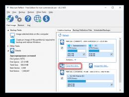
Removing the cover you will see printed circuit boards with various components. They are connected to each other by wire buses. The photo shows some devices with descriptions. We need to find the power board. It has a transformer and an inlet for the power cord, so it’s not difficult to find. The first thing you should pay attention to is the fuse, which is usually installed at the beginning of the circuit. The fuse can take different forms, such as a glass capsule with a conductor or a small plastic box in which the fuse is placed. In the second case, you must first remove the lid of the box (you can use tweezers or tweezers) to get to the fuse itself. Next you need to check the fuse with a tester or multimeter for breakage. If it blows, which often happens, then go to a radio store, buy the same fuse and just change it. If everything is fine with the fuse, then we check further along the circuit.
Another element that often breaks is the transformer itself. Such a fault is detected by measuring the voltage on the secondary winding. It is worth noting that not everyone can replace a transformer. If you are not sure that you can change it yourself, then it is better to take your receiver to a repairman, and if this does not seem difficult for you, then go for it.


Another malfunction is the failure of the electrolytic or oxide capacitor at the input due to drying out. To detect this breakdown, you need to have at least a little understanding of radio mechanics. A faulty capacitor is usually yellowish in color; there may also be a small brown spot on the board at the base of its legs. You can also compare the rated and measured capacitance of the capacitor to determine its health.
The diode bridge in the receiver converts alternating mains current into direct current.
The diode bridge may also break. This is easy to check, since semiconductor diode has one main function: to pass current in one direction, but not in the other.
In the case we are considering, the breakdown occurred with the transistor of the primary winding of the transformer. It has a heatsink to dissipate heat, so it's quite easy to find. The malfunction was discovered as follows: we measured the voltage at the emitter of the transistor, it was not there, the primary winding was not powered, which means that all other parts were de-energized. The cost of the transistor is about 30 rubles. To replace it we need a soldering iron. We fix the problem, and – “Hurray! It’s working!” – the receiver is ok again. Note that the transistor does not break down often; most receivers fail due to a fuse.
Let's look at another very common malfunction - a firmware crash. This happens quite often. A sign of a firmware crash is complete freeze receiver. Then we just need a receiver.
The cause of receiver failure can also be poor-quality, unprofessional installation. If the external insulation of the cable is broken, then rainwater or snow can easily penetrate inside the cable and, like a hose, seep into the receiver, flooding all its internal contents. Therefore, you need to monitor the cable to see if there are any kinks or insulation damage.
For those who don't understand anything about internal structure satellite receivers, or who have no time to deal with this at all, should not despair if the device breaks down. No one has canceled service centers yet. You can go there with your problem and specialists will help you solve it.

They fail for various reasons - this is a voltage drop, wear and tear of the device itself due to intensive use, and failure certain elements. This also includes breakdowns caused by owners who decided to figure out the problem themselves without having special skills, for example, they incorrectly replaced the firmware in a satellite or cable receiver.
The power supply is perhaps the most broken part of the receiver. The power supply may break due to a poor-quality power supply network or low-quality radio components (especially on cheap Chinese equipment).
Dust and dirt can also cause the receiver to break down, creating an incorrect thermal condition.

IN service center Repair and maintenance of various satellite equipment is carried out. Moreover, repairs are carried out by specialists and using professional equipment. Almost any faulty part can be replaced with a new one. The timing of repairs will depend on the availability of parts at the service center. If any part is missing, it will be ordered from suppliers, which will take some time. But in large serious centers, usually, parts are always available.
Let's consider another situation: the receiver failed after a power surge. After opening the lid, it was discovered that the following parts had burned out:
- network capacity C5 - 47µFx400V
- Q1 - CS2N60F
- R8, R11, R13 – each 3 Ohm (size 1206)
- R9 - 47 Ohm (1206)
- U1 – type not defined
We found a page on the Internet with a table on identification and selection of analogues (for example, http://remont-aud.net/ic_power/), using it we look at what we have and what we don’t. Let's replace the last part with SG6848 to minimize interference with the factory circuit.
We dismantle the faulty parts (circled in red in the photo):
- R8, R11, R13 - 3 Ohm (1206)
- R3, R6 (one of them is possible) - 1 MOm (1206)
- C3 - 68nF
- R25 - 3.6 kOm (0805)
- R26 - 10 kOm (0805)
Installing new parts:
- instead of U1 - SG6848
- instead of R8, R11, R13 - one resistor 1.8 Ohm x 0.5W
- instead of C3 there is a 100 kOm resistor (1206)
- instead of R26 there is a 33 kOm resistor
- instead of R25, we select a resistor in the range of 10-12 kOm, controlling the voltage 3V3 at the cathode VD8, we will settle on a nominal value of 11 kOm, U = 3.36V (at 10 kOm U = 3.28 V, at 12 kOm U = 3.41 V)
- instead of the burned-out Q1 - SSS4N60B (TO-220F housing).


Video review: repair of the Tricolor GS8300 receiver (no signal)
———————
From June 28, 2011, all subscribers using the GS-8300, GS-8300M and GS-8300N receivers need to update the software via satellite to version 1.0.157.