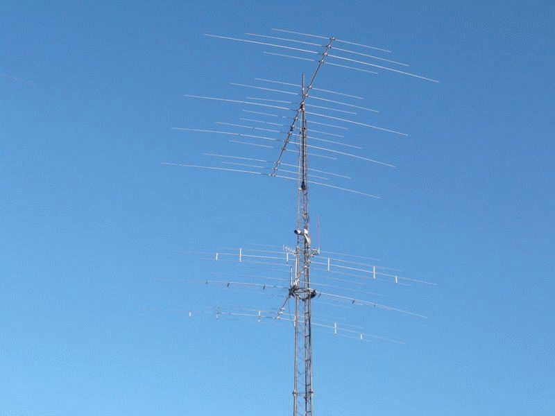
Dish antenna for HF bands. All-wave antenna of the “poor” radio amateur
Capital structures and balcony fencing can be successfully used to secure the antenna in cases where installing this device on the roof of a building is not possible for some reason. Of course, a HF balcony antenna cannot be compared in efficiency to a basic one, but for many tasks its capabilities will be quite acceptable. In this article we will look in detail at a number of issues related to the operation of this kind of antennas and learn how to make them yourself.
catch the wave
Today, balcony antennas can often be seen on the facades of city high-rise buildings. Almost all of them are designed to operate in the shortwave range. With the help of such antennas you can receive radio and television broadcast signals, and they also allow you to use radio stations for amateur or commercial (professional) radio communications. It should be noted that such devices perform better reception of radio signals than transmission.
A homemade HF balcony antenna can always be fixed on elements of a metal sheathing, since it is light in weight and has small overall dimensions. Just first make sure that the device clearly receives the signal you need. The fact is that, due to the shielding properties of the building, the balcony antenna works effectively only in some directions, and if your balcony or loggia “looks” in the direction opposite to the signal source, it may turn out to be absolutely useless.
What radio waves are called short? This category includes electromagnetic radiation with wavelength from 10 to 100 m. These lengths correspond to the frequency range 3 – 30 MHz. A remarkable property of these radio waves is their ability to be reflected from the surface of the earth and the upper layers of the atmosphere, practically without losing power. Thanks to this, the wave flows around the surface of the planet, which makes it possible to transmit signals over long distances.
If you notice a deterioration in the quality of communication, do not rush to scrap the antenna. Radio communication on short waves is very sensitive to many factors, among which the main ones are time of day, weather conditions and the nature of solar activity. These factors have a particularly noticeable effect on the reception and transmission of signals by a balcony antenna, which is inferior in its capabilities to the basic one. Another reason for changes in signal level is interference. Waves from the same source reach the antenna along different trajectories, having, accordingly, different durations. This is what causes this phenomenon.
We design an antenna for the HF range
Those whose hand reaches for a soldering iron instead of a toothbrush in the morning will probably be interested in how to make homemade antenna from scrap materials. First of all, we need a ferrite tube– shielding element of cables from monitors and keyboards. One of the radio amateurs accidentally discovered that such tubes react with a reactive impedance within a few hundred Ohms to radio signals with a wavelength of just under 100 m. At the same time, a broadband transformer on such tubes demonstrates good frequency characteristics within the shortwave range. These properties of ferrite tubes will help us design a HF antenna for a balcony or loggia. To do this, you need to follow the step-by-step instructions:
After installation on the balcony, such a homemade HF antenna demonstrates good reception of signals with a frequency of 14 to 28 MHz.
Read about it in our article. It also offers other models such as floor-mounted and ceiling-mounted.
If you are wondering: then you will find the answer on our website.
Setting up amateur communications
In the territory Russian Federation There are two open radio frequency ranges:
— CB range(Latin letters, marking reads “si-bi”), which is short-wave;
— PMR or LPD range, which is ultra-short wave.
They are called open because they can be used without special permission. However, there is one caveat: commercial use of the PMR range is not allowed.
CB waves (27 MHz) can bend around buildings, natural hills and forests. They are characterized by insignificant losses, so connecting the antenna to the radio station can be done using even cheap brands of cable. Installing base antennas for operation in the CB band is not contrary to law.
CB frequencies are characterized by the long-range effect, which is caused by changes in solar activity or in the state of our planet's magnetic field. It lies in the fact that a signal from a source located 10–15 thousand km away is received more clearly than from a station operating several kilometers away.
Ultrashortwave signals (PMR and LPD) are transmitted at a frequency of 433 to 446 MHz. A mobile radio station operating on the LPD band is perfect for organizing communications, for example, between an office and a warehouse. Unlike equipment designed for the CB band, such stations support multi-channel communication mode and are equipped with very efficient built-in antennas. In addition, LPD stations can be used to organize communication within a building, and their signals can even reach the basement.
Tip: To listen to and communicate with other ham radios, your best bet is to use an AM/FM radio with a CB base antenna. Such equipment will give you the opportunity to listen to both local stations and foreign radio broadcasts.


The design of this antenna was told to me over the air about 10...15 years ago by radio amateur V. Voliy (UA6DL), for which I am very grateful to him. The antenna still works, and in principle I am satisfied with its performance as a backup antenna. The measured SWR values for a frequency of 1.9 MHz are 1.9; for 3.6 MHz - 1.3; for 7.05 MHz-1.2; for 14.1 MHz -1.4; for 21.2 MHz -1.7; for 28.6 MHz - 1.6. The antenna design is shown in Fig. 1. The antenna is an ordinary dipole with a beam length of 20.5 m. The antenna is powered by a coaxial cable with a characteristic impedance of 50...75 Ohms. Broadband is used for matching matching device on a ferrite ring and a two-wire line with a characteristic impedance of 300 Ohms. The two-wire line is made of TV cable CATV 17.7 m long, open at the end. The broadband transformer is made on a ferrite ring of grade 30...50 HF with an outer diameter of 24...32 mm - depending on the transmitted power (1 cm of the cross-section of the ring core is capable of transmitting about 500 W without damage). If one ring is not enough, take two or three rings folded together. The ring(s) are pre-wrapped with fluoroplastic tape. At maximum power, the ring can heat up to 70°C. The transformation ratio of the broadband transformer is 1:4. To make a transformer, a PEV 00.8...1.0 wire folded in parallel or a stranded wire in vinyl or fluoroplastic insulation (not afraid of heating) is wound around the ring. The number of turns is 9...10. After winding, the end of one wire is connected to the beginning of the other, forming a midpoint. The broadband transformer is mounted at a distance of 5.9 m from the point of connection of the dipole to two-wire line. The transformer is protected from moisture by wrapping it with insulating material and varnishing it. The antenna fabric is made of galvanized wire dia. 2 mm, and, apparently, that’s the only reason it stood so long long time in the acid rain conditions of Donbass.
Rice. 1
In principle, the antenna arms can be made from 5...8 twisted copper wires of PEV grade 0.8 mm. Tested - good strength. Horizontal wire wave channel. As amateur radio wisdom says, best amplifier high frequency in the transceiver (receiver) is the antenna. And this is 100% true! Having a good antenna, you can even work with a home-made transceiver with DX, and vice versa, you cannot “pull out” the same high-frequency correspondents with “weak” correspondents with an expensive imported transceiver and a bad antenna. Directional antennas are widely used for these purposes, since they make it possible to concentrate most of the emitted electromagnetic energy in a certain direction, thereby increasing the field strength at the receiving location and reducing interference in other directions, as well as receiving a higher signal level when receiving from this direction. Of course the best option is to install a rotating directional antenna, but not all shortwave operators can afford to purchase and install such an antenna.

Fig.2
I propose the design of a compromise version of a single-band two-element “Wave Channel” antenna (Fig. 2) with a fixed radiation pattern. The antenna is located in a horizontal plane and has clearly defined directional properties. The design of the antenna is clear from the figure. In this antenna, one active vibrator is a half-wave dipole, the second passive vibrator is the director. The current in a passive vibrator is created due to electromagnetic induction by the field of the active vibrator. By changing the length of the passive vibrator and its distance from the active vibrator, you can change the relative phase of the current in it. This is the basis of the principle of concentration of electromagnetic energy in a certain direction. If the phase of the current in a passive vibrator is such that the resulting field in the direction of this vibrator increases, and in the opposite direction it decreases, the passive vibrator works as a director. Such an antenna provides a power gain of about 5 dB. The reduction of interference from radio stations located perpendicularly and behind the direction towards the correspondent is also significant, which for this antenna is approximately 15 dB. An antenna made according to the given dimensions, as a rule, does not need to adjust the length of the elements and the distance between them. The antenna fabric is made of copper rope, copper, galvanized or bimmetallic wire, dia. 2 mm. If such wire is not available, you can make a homemade copper rope from 6...8 PEV-I or PEV-II 0.7...0.8 mm wires twisted in increments of 2-3 turns per 1 cm. The ends of the rope should be well soldered. This homemade wire rope is quite durable. Naturally, before installing this antenna, the radio amateur must determine for himself the most interesting direction of radiation (reception). Structural dimensions antennas for each range are given in Table 1.
The antenna fabric itself is attached to stationary supports using a nylon (synthetic) cord, which can be buildings, residential buildings, tall trees, etc. Porcelain nut insulators are used as insulators. However, if such insulators cannot be purchased, they can be successfully replaced by homemade insulators made from textolite or getinax. To make them, take an insulating block (parallelepiped made of textolite, getinax, etc.) of suitable dimensions, and two holes are drilled in it along the diameter of the wire at an angle of 90°. Homemade insulators must work in compression. Insulation strips made of bamboo (pine, getinax or textolite) serve as distance clamps (spacers) between the director and the active element. All cord connections are made only with viscous knots. To protect against moisture, insulators and spacers are coated with insulating varnish. The design of these insulators is shown in Fig. 3.

Rice. 3
Simple, effective G3XAP antenna for 160 and 80 m.
Long-distance communication on short waves is carried out due to the so-called spatial wave, which is reflected by the ionosphere and can have both vertical and horizontal polarization. When operating on the 160 and 80 m bands, shortwave radio amateurs use both ground waves and sky waves. That is why it is desirable for this range to have an antenna with vertical radiation. Since a vertical quarter-wave vibrator for the 160 m range is difficult to imagine even in the imagination (its height should be about 40 m!), the antenna for low-frequency ranges has to be made as a compromise. Its emitter consists of horizontal and vertical conductors (Fig. 4), or the emitter is placed at an angle to the horizon.

Rice. 4
Naturally, the greater the height of the vertical part of the antenna, the higher its efficiency. In addition, the efficiency of a vertical U4 antenna largely depends on the quality of the grounding. It is best to use special grounding - a pin driven into damp ground, a buried sheet of galvanized iron, etc. As a last resort, you can use metal structures fixed in the ground. It is unacceptable to use water supply and heating pipes as such grounding, because In addition to the poor quality of such grounding, severe interference with radio and television reception is possible, as well as burns from high-frequency currents for people who touch the pipelines. The proposed antenna was repeated by Yuri in the late 80s, US31VZ, ex RB41VZ. Actively operating SSB on the 160m band, in one year he received QSL from 150 regions of the former USSR. US3IVZ uses this antenna without counterweights. For more efficient work it must have counterweights. A 2-inch diameter steel pipe is mounted on a small support insulator, which can be used as porcelain insulator used in electrical installations, or simply by placing a sheet of insulating material under the vertical pipe. To tune the antenna, use a variable capacitor C^^=500 pF, which has a gap between the plates of at least 1...2 mm (depending on the PA power). The quality of matching is judged by the readings of the SWR meter. The input impedance of such an antenna is approximately 60 Ohms (depending on the quality of the ground), so it is advisable to power it with a coaxial cable with a characteristic impedance of 50 Ohms. With careful tuning of the antenna, we can achieve SWR = 1.1...1.2. The antenna dimensions are given in Table 2.
|
Range, m |
||
V. BASHKATOV, USOIZ, Gorlovka, Donetsk region.
Literature
1. S.G.Bunin, L.P.Yaylenko. Shortwave Radio Amateur's Handbook. - Kyiv, "Technology", 1984.
The frequency range 1-30 MHz is traditionally called shortwave. On short waves you can receive radio stations located thousands of kilometers away.
Which antenna to choose for shortwave reception
No matter which antenna you choose, it is best for it to be external(outdoor), highest positioned and away from power lines and metal roofs (to reduce interference).
Why is the outdoor one better than the indoor one? There are many sources in a modern apartment and apartment building electromagnetic field, which are such a strong source of interference that the receiver often receives only interference. Naturally, the external one (even on the balcony) will be less susceptible to these interferences. In addition, reinforced concrete buildings shield radio waves, and therefore the useful signal indoors will be weaker.
Always use coaxial cable to connect the antenna to the receiver, this will also reduce the level of interference.
Receiving antenna type
In fact, on the HF band type receiving antenna not so critical. Usually a 10-30 meter long wire is sufficient, and a coaxial cable can be connected at any convenient location on the antenna, although to ensure greater broadband (multi-band), it is better to connect the cable closer to the middle of the wire (you will get a T-antenna with shielded reduction). In this case, the braid of the coaxial cable is not connected to the antenna.
Wire antennas
Although more long antennas can receive more signals, they will also receive more interference. This somewhat equalizes them with short antennas. In addition, long antennas overload ("phantom" signals appear throughout the entire range, the so-called intermodulation) household and portable radios with strong signals from radio stations, because they are small compared to amateur or professional radios. In this case, you need to turn on the attenuator in the radio receiver (set the switch to the LOCAL position).
If you are using a long wire and connecting to the end of the antenna, it would be better to use a 9:1 matching transformer (balun) to connect the coaxial cable, because The “long wire” has a high active resistance (about 500 Ohms) and such matching reduces losses on the reflected signal.


Matching transformer WR LWA-0130, ratio 9:1
Active antenna
If you do not have the opportunity to hang an external antenna, then you can use an active antenna. Active antenna- this is, as a rule, a device that combines a loop antenna (either ferrite or telescopic), a broadband low-noise high-frequency amplifier and a preselector (a good active HF antenna costs over 5,000 rubles, although for household radios there is no point in purchasing an expensive one, something will do just fine like Degen DE31MS). To reduce interference from the network, it is better to choose an active antenna that runs on batteries.
The point of an active antenna is to suppress interference as much as possible and amplify the desired signal at the RF (radio frequency) level without resorting to conversion.
In addition to the active antenna, you can use any indoor antenna that you can make (wire, frame or ferrite). In reinforced concrete houses indoor antenna It should be located away from electrical wiring, closer to the window (preferably on the balcony).
Magnetic antenna
Magnetic antennas (loop or ferrite), to one degree or another, under favorable circumstances, can reduce the level of “urban noise” (or rather, increase the “signal-to-noise” ratio) due to their directional properties. Moreover, the magnetic antenna does not receive the electrical component of the electromagnetic field, which also reduces the level of interference.

By the way, EXPERIMENT is the basis of amateur radio. External conditions play a significant role in the propagation of radio waves. What works well for one radio amateur may not work at all for another. The most visual experiment of radio wave propagation can be carried out with a decimeter television antenna. By rotating it around the vertical axis, you can see that the highest quality image does not always correspond to the direction towards the television center. This is due to the fact that radio waves, when propagating, are reflected and “mixed with others” (interference occurs) and the highest quality signal comes from the reflected wave, and not from the direct one.
Grounding
Don't forget about grounding(through the heating pipe). Do not ground to the protective conductor (PE) in the socket. Old tube radios especially “love” grounding.

Jokes
Anti-radio interference
In addition to this, to combat interference and overloads, you can use preselector(antenna tuner). Using this device can suppress out-of-band interference and strong signals to a certain extent.
Unfortunately, in the city all these tricks may not give the desired result. When you turn on the radio, you can only hear noise (as a rule, the noise is stronger in the low frequency ranges). Sometimes novice radio observers even suspect their radios of malfunction or unworthy performance. It's easy to check the receiver. Disconnect the antenna (fold the telescopic antenna or switch to an external one, but do not attach it) and read the S-meter reading. After this, extend the telescopic antenna or connect an external one. If the S-meter readings have increased significantly, then everything is in order with the radio receiver, and you are out of luck with the receiving location. If the interference level is close to 9 points or higher, normal reception will not be possible.
Finding and identifying the source of interference
Alas, the city is full of “broadband” interference. Many sources generate broad spectrum electromagnetic waves, like a spark discharge. Typical representatives: impulse blocks power supply, commutator electric motors, cars, electric lighting networks, networks cable television and the Internet, Wi-Fi routers, ADSL modems, industrial equipment and much more.
The easiest way to “search” for the source of interference is to examine the room using a pocket radio (no matter what range, DV-SV or HF, just not the FM range). Walking around the room, you can easily notice that in some places the receiver is noisier - this is the “localization location” of the interference source. Almost everything connected to the network (computers, energy-saving lamps, network wires, charging device etc.), as well as the electrical wiring itself.
It is in order to somehow reduce the harmful effects of urban interference that “super-duper” sophisticated radios and transceivers have become popular. A city radio amateur simply cannot work comfortably on household equipment that performs well “in the wild.” Greater selectivity and dynamics are required, and digital processing signal (DSP) allows you to “work wonders” (for example, suppress tonal interference) that are inaccessible to analog methods.
Of course, the best HF antenna is directional (wave channel, QUARD, traveling wave antennas, etc.). But let's be realistic. Building a directional antenna, even a simple one, is quite difficult and expensive.
Paris?! I took it!
Washington?! I took it!
And after you climbed there, the receiver stopped receiving distant radio stations,” my father told me as a child.
Several decades have passed since then, and the receiver, as if nothing had happened, continues to take over cities. To be honest, I didn’t do anything with the receiver. These Soviet lamp units will continue to work after the apocalypse. It's just all about the antenna.
Late in the evening, in the glow of the fireplace flame, without turning on the electricity, I press the key of the old tube radio, the luminous scale with cities comfortably saturates the twilight of the room, rotating the vernier, I tune in to the radio station.
The long wave range is silent. True, exactly in the rectangle of the scale of the luminous window of the city of Warsaw, at a frequency of about 1300 meters, the radio station “Polish Radio” was taken, and this is a straight line range of more than 1150 km.
Medium waves are picked up by local and distant radio stations. And here we take a range of more than 2000 km.
For almost 2 years now, in Moscow and the region, central radio broadcasting channels have stopped working on these waves (DV, SV).
Short waves are especially lively; there is a full house here. On short waves, radio waves can travel around the Earth and radio stations can actually be received from anywhere on the globe, but the conditions for the propagation of radio waves here depend on the time and state of the ionosphere from which they can be reflected.
I turn on the table lamp and on all bands (except VHF) instead of radio stations there is continuous noise, turning into rumble. Now the table lamp, including the power cables, is an interference transmitter that interferes with normal radio reception. Currently fashionable energy-saving lamps and other household appliances (TVs, computers) have turned network wires into antennas for interference transmitters. As soon as the network wire from the lamp was moved a couple of meters away from the antenna lowering wire, the reception of radio stations resumed.
The problem of noise immunity existed in the last century, and in the meter wavelength range it was solved by various antenna designs, which were called “anti-noise”.
Anti-noise antennas.
I first read a description of anti-noise antennas in the magazine “Radiofront” for 1938 (23, 24).
 |
| Rice. 2. |
 |
| Rice. 3. |
A similar description of the design of an anti-noise antenna was published in the magazine “Radiofront” for 1939 (06). But here good results obtained in the long wavelength range. The amount of interference attenuation was 60 dB. This article may be of interest for amateur radio communications on the Far East (136 kHz).
True, at present the best results are obtained by using a matching amplifier directly in the antenna, which coaxial cable connected to a matching amplifier at the input of the receiver itself.
Broom antenna.
This was my first homemade antenna, which I made for a detector receiver. The first antenna that I burned myself on, tinning each wire, setting the angles of the rods strictly according to the drawing using a protractor. No matter how hard I tried, but detector receiver didn't work with her. If I had then put a saucepan lid instead of a broom, the effect would have been similar. Then, in childhood, the receiver was saved by the network wiring, one wire of which was connected to the detector input through an isolation capacitor. That’s when I realized that for normal operation of the receiver, the length of the antenna wire must be at least 20 meters, and let all sorts of electronic clouds conducting layers of air above the panicle remain in theory. Old-timers will still remember that the broom attached to the chimney caught exceptionally well when the smoke went vertically upward. In villages, they usually lit the stove in the evening and cooked dinner in cast iron pots. In the evening, as a rule, the wind subsides and smoke rises in a column. At the same time, in the evening, waves are refracted from the ionized layer of the earth's surface and reception in these wave ranges improves.
top scores can be obtained with the antenna pictures below (Figure 5 - 6). These are also antennas with lumped capacitance. Here the wire frame and spiral includes 15 - 20 meters of wire. If the roof is high enough and not made of metal and freely transmits radio waves, then such compositions (Fig. 5, 6) can be placed in the attic.
 |
| Rice. 5. "Radio to everyone" 1929 No. 11 |
 |
| Rice. 6. "Radio to everyone" 1929 No. 11 |
Roulette antenna.
I used a regular construction tape with a steel sheet length of 5 meters. This tape measure is very convenient as an HF antenna, since it has a metal clip electrically connected through the shaft to the tape web. Pocket HF receivers have a purely symbolic whip antenna, otherwise they would not fit in a pocket. As soon as I attached the tape measure to the whip antenna of the receiver, the shortwave bands in the region of 13 meters began to choke on large quantity received radio stations.
Reception to the lighting network.
This is the title of an article in the Radio Amateur Magazine for 1924 No. 03. Now these antennas have gone down in history, but if necessary, you can still use network wires in some lost village, having first turned off all modern household appliances.Homemade L-shaped antenna.
These antennas are shown in Figure 4. a, b). The horizontal part of the antenna should not exceed 20 meters, usually 8 - 12 meters are recommended. The distance from the ground is at least 10 meters. A further increase in the height of the antenna leads to an increase in atmospheric interference.
I made this antenna from a network carrier on a reel. Such an antenna (Fig. 8) is very easy to deploy in the field. By the way, the detector receiver worked well with it. In the figure, which shows a detector receiver, an oscillating circuit is made from one network reel (2), and the second network extension (1) is used as an L-shaped antenna.
Loop antennas.
The antenna can be made in the form of a frame, and is an input tunable oscillating circuit that has directional properties, which significantly reduces interference to radio reception.Magnetic antenna.
In its manufacture, a ferrite cylindrical rod is used, as well as a rectangular rod, which takes up less space in a pocket radio. The input tunable circuit is placed on the rod. The advantage of magnetic antennas is their small size, high quality factor of the circuit, and, as a consequence, high selectivity (tuning out from neighboring stations), which, together with the directional property of the antenna, will only add another advantage, such as better noise immunity of reception in the city. The use of magnetic antennas is largely intended for receiving local radio broadcasting stations, however, the high sensitivity of modern receivers of the DV, MF and HF bands and the positive properties of the antenna listed above provide a good radio reception range.
So, for example, I was able to pick up a distant radio station using a magnetic antenna, but as soon as I connected an additional bulky external antenna, the station was lost in the noise of atmospheric interference.
 |
| The magnetic antenna in the stationary receiver has a rotating device. |
On a flat ferrite (similar in length to a cylindrical) rod measuring 3 X 20 X 115 mm, grade 400NN for the DV and SV ranges, coils are wound with PELSHO wire, PEL 0.1 - 0.14, on a movable paper frame, 190 and 65 turns each.
For the HF range, the contour coil is placed on a dielectric frame 1.5 - 2 mm thick and contains 6 turns wound in increments (with a distance between turns) with a circuit length of 10 mm. Wire diameter 0.3 - 0.4 mm. The frame with coils is attached to the very end of the rod.
Attic antennas.
I have been using the attic for television and radio antennas for a long time. Here, far from electrical wiring, the antenna of the MF and HF ranges works well. The roof made of soft roofing, ondulin, slate is transparent to radio waves. The magazine “Radio for Everyone” for 1927 (04) gives a description of such antennas. The author of the article “Attic antennas”, S. N. Bronstein, recommends: “The shape can be very diverse, depending on the size of the room. The total length of the wiring must be at least 40 - 50 meters. The material is antenna cord or bell wire, mounted on insulators. There is no need for a lightning switch with such an antenna.”
I used both solid and stranded wire from electrical wiring without stripping the insulation from it.
Ceiling antenna.
This is the same antenna that my father’s receiver used to pick up cities. A copper coil wire with a diameter of 0.5 - 0.7 mm was wound around a pencil and then stretched under the ceiling of the room. There was a brick house and a high floor, and the receiver worked excellently, but when they moved to a house made of reinforced concrete, the reinforcing mesh of the house became a barrier to radio waves, and the radio stopped working normally.
From the history of antennas.
Going back in time, I was interested to know what the world's first antenna looked like.
The first antenna was proposed by A. S. Popov in 1895; it was a long thin wire raised with balloons. It was attached to a lightning detector (a receiver that detects lightning discharges), a prototype of a radiotelegraph. And during the world’s first radio broadcast in 1896 at a meeting of the Russian Physical and Chemical Society in physical office Petersburg University from the first radiotelegraph radio receiver, to vertical antenna a thin wire was stretched (Radio magazine 1946 04 05 “First Antenna”).
 |
| Rice. 13. First antenna. |
The HF range contains a number of radio frequencies (27 MHz, commonly used by drivers), broadcasting many stations. There are no TV shows here. Today we will look at the amateur series used by various radio enthusiasts. Frequencies 3.7; 7; 14; 21, 28 MHz of the HF range, related as 1: 2: 4: 6: 8. It is important, as we will see later, it becomes possible to make an antenna that would catch all denominations (the issue of coordination is the tenth thing). We believe that there will always be people who will use the information, listen to the radio broadcasts. Today's topic is a DIY HF antenna.
We will disappoint many, today we will again talk about vibrators. Objects of the Universe are formed by vibrations (the views of Nikola Tesla). Life attracts life, it's movement. To give a wave life, vibrations are necessary. Changes in the electric field give rise to a magnetic response, so the frequency that carries information to the ether crystallizes. The immobilized field is dead. A permanent magnet will not generate a wave. Figuratively speaking, electricity is a masculine principle; it exists only in motion. Magnetism is a rather feminine quality. However, the authors delved into philosophy.
It is believed that horizontal polarization is preferable for transmission. Firstly, the azimuth radiation pattern is not circular (they said it in passing), there will certainly be less interference. We know that various objects such as ships, cars, tanks are equipped for communication. You cannot lose commands, orders, words. Will the object turn the wrong way, but is the polarization horizontal? We disagree with well-known, respected authors who write: vertical polarization has been chosen as a connection for an antenna of a simpler design. Touch the matter of amateurs, it is rather about the continuity of the heritage of previous generations.
Let's add: with horizontal polarization, the parameters of the Earth have less influence on the propagation of the wave; in addition, with vertical polarization, the front suffers attenuation, the lobe rises to 5 - 15 degrees, which is undesirable when transmitting over long distances. For antennas (monopoles) with vertical polarization, good grounding is important. The efficiency of the antenna directly depends. It is better to bury wires about a quarter wavelength long in the ground; the longer, the higher the efficiency. Example:
- 2 wires – 12%;
- 15 wires – 46%;
- 60 wires – 64%;
- ∞ wires – 100%.
Increasing the number of wires reduces the characteristic impedance, approaching the ideal (of the specified vibrator type) - 37 Ohms. Please note that the quality should not be brought closer to ideal; 50 Ohms do not need to be matched with the cable (in communication, RK - 50 is used). Great deal. Let's supplement the information package with a simple fact: with horizontal polarization, the signal is added to the one reflected by the Earth, giving an increase of 6 dB. Vertical polarization has so many disadvantages, they use it (it turned out interesting with grounding wires), and put up with it.
The design of HF antennas comes down to a simple quarter-wave, half-wave vibrator. The second ones are smaller in size and are less accepted; the second ones are easier to coordinate. The masts are placed vertically using spacers and guy wires. They described a structure hung on a tree. Not everyone knows: at a distance of half a wave from the antenna there should be no interference. Applies to iron and reinforced concrete structures. Wait a minute to rejoice, at a frequency of 3.7 MHz the distance is... 40 meters. The antenna reaches the height of the eighth floor. Creating a quarter-wave vibrator is not easy.
It’s convenient to build a tower to listen to the radio, we decided to remember the old way of catching long waves. You will find internal ferromagnetic antennas in Soviet-era receivers. Let's see if the designs are suitable for their intended purpose (catching broadcasts).

HF magnetic antenna
Let's say there is a need to accept frequencies of 3.7 - 7 MHz. Let's see if it is possible to design a magnetic antenna. It is formed by a core of round, square, rectangular cross-section. Sizes are recalculated using the formula:
do = 2 √ рс / π;
do is the diameter of the round rod; h, c - height, width of the rectangular section.
Winding is not carried out over the entire length; in fact, you need to calculate how much to wind and select the type of wire. Let's take the example of an old design textbook and try to calculate an HF antenna with frequencies of 3.7 - 7 MHz. Let's take the resistance of the receiver input stage to be 1000 Ohms (in practice, readers measure the input resistance of the receiver themselves), the parameter of the equivalent attenuation of the input circuit, at which the specified selectivity is achieved, is equal to 0.04.
The antenna we are designing is part of a resonant circuit. The result is a cascade endowed with some selectivity. How to solder, think for yourself, just follow the formulas. Those carrying out the calculation will need to find the maximum and minimum capacitance of the tuning capacitor using the formula: Cmax = K 2 Cmin + Co (K 2 – 1).
K – subband coefficient, determined by the ratio of the maximum resonant frequency to the minimum. In our case, 7 / 3.7 = 1.9. It is chosen from incomprehensible (according to the textbook) considerations; according to the example given in the text, let’s take it equal to 30 pF. We won't be much mistaken. Let Cmin = 10 pF, we find the upper adjustment limit:
Cmax = 3.58 x 10 + 30 (3.58 – 1) = 35.8 + 77.4 = 110 pF.
Rounded up, of course, you can take a variable capacitor of a larger range. The example gives 10-365 pF. Let's calculate the required inductance of the circuit using the formula:
L = 2.53 x 10 4 (K 2 – 1) / (110 – 10) 7 2 = 13.47 µH.
The meaning of the formula is clear, let us add that 7 is the upper limit of the range, expressed in MHz. Select the coil core. At the frequencies of the core, the magnetic permeability is M = 100; we select ferrite grade 100NN. We take a standard core 80 mm long, 8 mm in diameter. Ratio l / d = 80 / 8 =10. From reference books we extract the effective value of magnetic permeability md. That turns out to be 41.
We find the winding diameter D = 1.1 d = 8.8, the number of winding turns is determined by the formula:
W = √(L / L1) D md mL pL qL;
We read the formula coefficients visually using the graphs below. The figures will show the reference figures used above. Look for the brand of ferrite, man does not live by bread alone. D is expressed in centimeters. The authors obtained: L1 = 0.001, mL = 0.38, pL = 0.9. Let's calculate qL using the formula:
qL = (d / D) 2 = (8 / 8.8) 2 = 0.826.
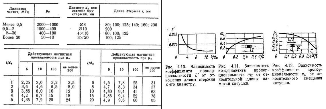
We substitute the numbers into the final expression for calculating the number of turns of a ferrite HF antenna, and it turns out:
W = √ (13.47 / 0.001) x 0.88 x 41 x 0.38 x 0.9 x 0.826 = 373 turns.
The cascade must be connected to the first receiver amplifier, bypassing the input circuit. Let's say more, we have now calculated the means of selectivity in the range of 3.7-7 MHz. In addition to the antenna, it simultaneously turns on the input circuit of the receiver. Therefore, it will be necessary to calculate the coupling inductance with the amplifier, fulfilling the conditions for ensuring selectivity (we take typical values).
Lsv = (der - d) Rin / 2 π fmin K 2 = (0.04 - 0.01) 1000 / 2 x 3.14 x 3.7 x 3.61 = 0.35 μH.
The transformation coefficient will be m = √ 0.35 / 13.47 = 0.16. We find the number of turns of the communication coil: 373 x 0.16 = 60 turns. We wind the antenna with PEV-1 wire with a diameter of 0.1 mm, and we wind the coil with PELSHO with a diameter of 0.12 mm.
Many people are probably interested in several questions. For example, the purpose of Co formulas for calculating a variable capacitor. The author bashfully avoids the question, supposedly the initial capacity of the circuit. Hardworking readers will calculate the resonant frequencies of a parallel circuit in which an initial capacitance of 30 pF is soldered. We will make a slight mistake by recommending placing a 30 pF trimmer capacitance next to the variable capacitor. The chain is being fine-tuned. Beginners are interested in the electrical circuit, which will include a homemade HF antenna... The parallel circuit, the signal from which is removed by a transformer, is formed by wound coils. The core is common.
An independent HF antenna is ready. You will find this in a tourist radio (models with a dynamo are popular today). HF antennas (and even more so SW) would be large if the design was made in the form of a typical vibrator. Such designs are not used in portable equipment. The simplest HF antennas take up a lot of space. Better reception. The purpose of the HF antenna is to improve signal quality. In the apartment, loggia. They told us how to make a miniature HF antenna. Use vibrators in the country, in the field, forest, and open areas. Material provided by the design reference book. The book is full of errors, but the result seems to be passable.
Even old textbooks suffer from typos missed by editors. This applies to more than one branch of radio electronics.