Refurbishment of a table lamp. Driver for LEDs from an energy-saving lamp Table lamp conversion to LED connection
If an old Soviet lamp with fluorescent lamps daylight type LB-40, LB-80 is out of order, or you are tired of changing the starter in it, disposing of the lamps themselves (but you can’t just throw them in the trash for a long time), then it can easily be converted into LED.
Most importantly, fluorescent and LED lamps have the same base - G13. No upgrade of the housing, unlike other types of pin contacts, is required. 
- G- means that pins are used as contacts
- 13 is the distance in millimeters between these pins

Rework Benefits
In doing so, you will receive:

- greater illumination
- lower losses (almost half of the useful energy in fluorescent lamps can be lost in the inductor)
- lack of vibration and nasty rattling sound from the ballast throttle
 True, in more modern models, electronic ballast is already in use. They increased efficiency (90% or more), noise disappeared, but energy consumption and luminous flux remained at the same level.
For example, new models of such LPO and LVO are often used for Armstrong ceilings. Here is a rough comparison of their effectiveness: 
Another advantage of LED - there are models designed for supply voltages from 85V to 265V. For fluorescent you need 220V or close to it. 
For such Led, even if the mains voltage is weak or too high, they will start up and shine without any complaints.
Luminaires with electromagnetic control gear
What should I pay attention to when converting simple fluorescent fixtures to LED? First of all, its design. 
If you have a simple old Soviet-style lamp with starters and an ordinary (not electronic gear) throttle, then in fact you don’t need to upgrade anything. 
Just pull out the starter, select a new one according to the overall size led lamp, insert it into the case and enjoy brighter and more economical lighting.

If the starter is not removed from the circuit, then when replacing the LB lamp with an LED one, a short circuit can be created.
The throttle does not need to be removed. For LED, the current consumption will be within 0.12A-0.16A, and for the ballast, the operating current in such old lamps is 0.37A-0.43A, depending on the power. In fact, it will play the role of an ordinary jumper. 
After all the alteration, the lamp you have remains the same. There is no need to change the mount on the ceiling, and the burned-out lamps will no longer have to be disposed of and look for special containers for them. 
For such lamps, separate drivers and power supplies are not needed, since they are already built-in inside the case. 
The main thing is to remember the main feature - for LEDs, two pin contacts on the base are rigidly connected to each other.

And in luminescent they are connected by a filament. When it is heated, the mercury vapor ignites. 
In models with electronic control gear, no filament is used and the gap between the contacts is broken by a high voltage pulse.
The most common sizes of such tubes:
- 300mm (used in table lamps)

- 900mm and 1200mm
The longer their length, the brighter the glow. 
Alteration of the lamp with electronic control gear
If you have a more modern model, without a starter, with an electronic ballast (electronic ballast), then you will have to tinker a bit with changing the circuit. 
What is inside the lamp before alteration:
- throttle
- wires
- contact pads-cartridges on the sides of the case
The choke is what needs to be thrown out first. Without it, the entire structure will significantly lose weight. Unscrew the mounting screws or drill out the rivets, depending on the fastener.
Then disconnect the power wires. You may need a narrow-bladed screwdriver to do this. 
You can wire these and just have a bite to eat with pliers.
The connection diagram of the two lamps is different, on the LED everything is done much easier: 
The main task that needs to be solved is to apply 220V to different ends of the lamp. That is, the phase is on one output (for example, the right one), and zero on the other (left). 
Earlier it was said that for an LED lamp, both pin contacts inside the base are interconnected by a jumper. Therefore, here it is impossible, as in a fluorescent one, to supply 220V between them.
Use a multimeter to verify this. Set it to the resistance measurement mode, and touch the two leads with the test probes to measure. 
The display should show the same values as when the probes are connected to each other, i.e. zero or close to it (taking into account the resistance of the probes themselves).
The fluorescent lamp, between the two terminals on each side, has the resistance of the filament, which, after applying a voltage of 220V through it, warms up and “starts” the lamp. 
- without dismantling cartridges
- with dismantling and installation of jumpers through their contacts
without dismantling
The easiest way is without dismantling, but you will have to buy a couple of Wago clamps.
In general, you bite out all the wires suitable for the cartridge at a distance of 10-15mm or more. Then put them into the same Vago clamp. 
Do the same with the other side of the lamp. If the wago terminal block does not have enough contacts, you will have to use 2 pcs. 
After that, all that remains is to apply phase to the clamp on one side, and zero on the other.
No Vago, just twist the wires under the PPE cap. With this method, you do not need to deal with the existing circuit, with jumpers, climb into the contacts of the cartridges, etc.
With the dismantling of cartridges and the installation of jumpers
Another method is more scrupulous, but does not require any extra costs.
Remove the side covers from the lamp. This must be done carefully, because. in modern products, the latches are made of fragile and brittle plastic. 
After that, you can dismantle the contact cartridges. Inside them are two contacts that are isolated from each other.
Such cartridges can be of several varieties: 
All of them are equally suitable for lamps with a G13 base. They may have springs inside. 
First of all, they are not needed for better contact, but so that the lamp does not fall out of it. Plus, due to the springs, there is some compensation for the size of the length. Since with an accuracy of up to a millimeter, it is not always possible to make identical lamps.
There are two power wires for each cartridge. Most often, they are attached by snapping into special screwless contacts. 
Turn them clockwise and counterclockwise, and with an effort pull out one of them. 
As mentioned above, the pins inside the connector are isolated from each other. And by dismantling one of the wires, you actually leave one contact socket out of your hands. 
All current will now flow through the other pin. Of course, everything will work on one, but if you are making a lamp for yourself, it makes sense to slightly improve the design by placing a jumper.
Thanks to her, you do not have to catch the contact by turning the LED lamp around. The double connector ensures a secure connection. 
The jumper can be made from the extra power wires of the lamp itself, which you will definitely have as a result of the alteration.
With a tester, you check that after installing the jumper, there is a circuit between the previously isolated connectors. Do the same with the second plug-in contact on the other side of the lamp.
The main thing is to make sure that the remaining power wire is no longer phase, but zero. You bite the rest.
Fluorescent lamps for two, four or more lamps
If you have a two-lamp lamp, it is best to supply voltage to each connector with separate conductors. 
When installing a simple jumper between two or more cartridges, the design will have a significant drawback.
The second lamp will glow only if the first one is installed in its place. Remove it, and the other one will immediately go out. 
The supply conductors must converge on the terminal block, where in turn you will have connected: 
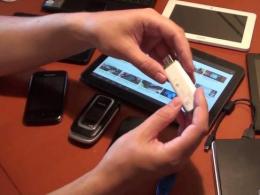
The modern small-sized table lamp, which is shown in the photograph, with a light source installed in it in the form of a fluorescent U-shaped compact lamp, worked for several years and failed.
According to the owner of the table lamp, recently, when the lamp was still working, an unpleasant smell was coming from its base.

Opening the base of the lamp immediately showed what the malfunction was. Insulation burned in one of the windings of the ballast device. Obviously, due to overheating or poor quality of the insulation of the winding wire of the coil, a short circuit occurred between the turns, which provoked the heating of the winding to a high temperature and the final failure of the ballast device.
I didn’t want to bother with rewinding the coils, and it’s almost impossible to find a ready-made ballast device for replacement, especially since its type was unknown. Therefore, I decided to remake the table lamp in a modern way - to install instead of fluorescent lamp LEDs, and replace the ballast electronic driver, especially since everything was at hand for such a rework.
Replacing a fluorescent lamp with LEDs
There was a long and narrow printed circuit board with LEDs from a linear LED lamp.
The driver in it burned out and melted the body-tube from heating. Therefore, the linear lamp was not subject to repair, and the diodes were serviceable. In width, the bar with LEDs just fit well into the reflector of the table lamp.


The luminescent U-shaped tube was held in the reflector by a plastic retainer and a plinth. To determine the required length of the LED strip, the lamp with the base had to be removed. In order to get to the base of the fluorescent lamp, I had to unscrew one screw and remove the fixing bar.

The base did not have an additional fastening, and to remove it, it remained only to unsolder the two supply wires. The wires were stranded of sufficient cross section, so I decided to leave them to supply voltage to the LEDs.

After fitting and determining the length of the LED strip, a piece of the required length was sawn off with a jigsaw. The LEDs on the bar are placed diagonally, so I had to cut with a jigsaw.

The cutting line passed in the right place, the printed tracks connecting the LEDs remained intact.

The existing table lamp reflector fasteners were used to mount the LED bar. The fluorescent lamp was fixed with a plastic bracket screwed to the reflector with a self-tapping screw, and the fixing cover was screwed to the plastic stand.

In the bar between the LEDs, a hole with a diameter of 3 mm was drilled for a self-tapping screw and a sample was made for mounting to the rack. After checking the alignment of the mounting hole with the hole in the short rack, you can proceed to fix the bar with LEDs in the reflector.

Before the final installation of the bar with LEDs in the reflector, it is necessary to solder the wires to the pads on it. One of the wires was short, and it had to be increased by soldering and an insulating cambric was put on the junction. Since the wires were of the same color, after testing with a multimeter, the positive wire was marked on both sides with white cambric rings put on.
I used a pre-made PCB with LEDs. But such a board is easy to do with your own hands. Moreover, if you use modern single-watt LEDs, for example LED-SMD5730-1, then it is enough to solder only 3-5 pieces. You can also use an LED strip glued to a metal strip as a light source instead of individual LEDs. You will have to select a driver in each case individually.

The photo clearly shows how the printed circuit board with the LEDs installed on it is fixed in the reflector of the table lamp. In order for the bar to be removed from the bottom of the reflector at the long post (photo on the left), a cambric was put on it with a length equal to the height of the right short post.

Before fixing the LEDs in the reflector, they were tested by connecting to the driver. The current consumption was also measured. The photo shows a reflector with LEDs installed in it. It remains to attach the fixing cover, having previously put a piece of cambric on the protruding stand for its entire length. Thus, sandwiched between two pieces of tubes, the left edge of the bar will also be securely fixed.
Selection and wiring diagram of the driver
To supply voltage to the LEDs, a transformerless driver from a faulty E27 LED lamp was used, assembled according to the classical electrical circuit diagram.

In the photo you see the wiring to the driver. The black wires coming from the LED board are soldered to the positive and negative outputs of the driver. With the help of blue and yellow wires, a 220 V supply voltage is supplied to the driver.

Electrical circuit diagram driver is above. Capacitor C1 with a capacity of 0.8 uF limits the current to 57 mA. R1 and R3 limit the inrush current due to the charge of the capacitors at the moment the driver is connected to the network. The diode bridge VD1-VD4 rectifies the voltage, and the electrolytic capacitor C2 smoothes the ripple so that the LEDs do not blink at the mains frequency. A safety element is also installed in the driver circuit, most likely it is a barter, it smooths out current surges and at the same time is a fuse. If it is necessary to reduce or increase the supply current of the LEDs, then it will be necessary to reduce or increase the capacitance of the capacitor C1 accordingly. You can increase C1 even without soldering it out of the board, by soldering an additional capacitor in parallel to its terminals. At parallel connection capacitors, the total capacitance is equal to the sum of their capacitances, that is, it will increase and the current will also increase.

The constant current, which ensures the optimal brightness of the glow of the LEDs used, is 20 mA. LEDs on printed circuit board three are connected in parallel. Therefore, the current required for their operation according to such a switching circuit should be 60 mA. As you know, for long-term operation of LEDs, it is better that the flowing current is slightly less than the rated current. Therefore, the 57 mA current provided by the driver satisfies this requirement.
There were 60 LEDs on the bar. The measured voltage drop across each triad of LEDs was 2.48 V. Thus, the power consumed by the LEDs was 2.48 V × 20 pcs. × 0.057 A \u003d 2.8 W, which is equivalent to the glow power of an incandescent light bulb of 25 W. The generated illumination of a table lamp is quite sufficient when used as a standby light, night lamp, computer keyboard backlight or reading an e-book.

The weight of the driver is insignificant and therefore I did not fasten it rigidly, I simply grabbed it with a flexible plastic clamp by one of the racks for attaching the halves of the base. The standard table lamp switch was used as a switch. To complete the alteration of the table lamp, it remains only to fasten its base together with three self-tapping screws, and it will be possible to proceed with sea trials.

Table lamp tests showed good result. Thanks to the ability to tilt the stand and rotate the reflector in two planes, the table lamp allows you to direct the light flux to the desired lighting area.
The alteration allowed not only to restore the working capacity of the table lamp at no cost, but also turned the obsolete table lamp into a modern lamp with low energy consumption.
In any work, as well as during leisure, good light is needed. You can buy a lamp, but sometimes it is not cheap. In the store, instead of a finished lamp, you can purchase an LED strip. It is relatively inexpensive and cut into pieces of any length. If you put it in a case or fix it in another way, you get a homemade lamp with an LED strip. You can take such a lamp with you to a fishing tent. In field conditions, the LED lamp is connected to a car battery.
Scope of homemade LED lamps
Homemade LED lamps for LED strip can be used instead of the usual ones:
- illumination of the workplace when performing minor work in the workshop or garage;
- backlighting from above the aquarium (if the tape is waterproof or in a sealed case, then the lamp can be lowered into the water);
- illumination of seedlings or indoor plants in winter;
- night light or table lamp;
- illumination of switches and sockets;
- computer keyboard lighting;
- to replace fluorescent lamps.
On the Internet, you can find many other types of floor lamps and ceiling chandeliers made of LED strip with photos and videos, as well as reviews of people who collected and used such lamps.
Types and parameters of LED strips
LED strip color optionsLED strips are produced in different designs according to the type of security. They can be of different brightness and different colors, which is determined by the color temperature - from warm white (2700K) to cold (6800K), as well as colored or capable of changing their color - RGB tapes. This makes it possible to choose the type of device for specific purposes.
LED strip device
An LED strip is a flexible plastic strip with conductive strips applied to it. Two are located at the edges and are connected to them. The rest connect the LEDs and resistors to each other. They are arranged in groups - three LEDs connected in series, and a resistor that serves to limit the current flowing through them.
 LED Strip Parameters
 The strip itself can be cut into sections that are multiples of three LEDs. In these places there are marks indicating the place of the cut and the pads to which the wires are soldered or connected using connectors.
LEDs can be coated with silicone on one or both sides. This determines the degree of protection from external influences. FROM reverse side the adhesive layer is applied on the strip, as on double-sided tape. With it, the LEDs are attached to the base.
The most common supply voltage is DC, 12V. There are designs designed for connection to a voltage of 24V and higher, but these are not common designs.
Types of LEDs used
The LEDs and resistors in the tape are used in the SMD series, without leads. LEDs in production are used in various sizes, which determines the marking of the tape - 5050 and 3528. These numbers show the size of the LED in tenths of a millimeter
 Visual difference between 5050 and 3528
Expert opinion
Alexey Bartosh
Ask an expertThe larger the size, the higher the brightness and the current and power consumption. It also depends on the number of LEDs per meter of length.
Accordingly, the marking of the SMD 5050 tape with a density of 60 LEDs means that 60 LEDs are installed per meter of length. SMD LEDs 5050.
Controllers, power supplies for LED strips
 controller and power supply
 Since the LED strip is designed for a constant voltage of 12V, a power supply or controller is required for connection.
Important! When you turn on the LED strip in a 220 volt network, it will instantly burn out!
Power supplies are produced in different capacities and shapes. From low-power, tablet-like chargers to powerful metal-cased designs with built-in coolers.
 Power supply for LED strips
 Some power supplies are equipped with dimmers and remote controls remote control. RGB ribbons require an RGB controller to control the color.
There are models with WiFi control, with color and music effects, for example, ARILUX® AL-LC01.
If there is no special block available, then you can use:
- Any transformer with an output voltage of 12V. A diode bridge and a smoothing capacitor must be connected to the output.
- The power supply of the computer, both in the computer itself and separately.
- If 3-6 LEDs are needed, then a capacitor can be used to limit the current, as well as a diode bridge and a capacitor that smooths out the glow pulsations. This scheme is used in LED lamps installed instead of incandescent lamps. The capacitance of a capacitor can be calculated using an online calculator.
- Make a faulty energy-saving lamp out of the board.
- Connect 20 pieces of LED strip in series and connect through a diode bridge and a smoothing capacitor to a 220V network.
Preparation of materials and parts
 making a lamp with your own hands
 Before starting work, you need to determine the required number and brightness of the LED strip, as well as the power of the power supply.
First of all, you need to determine the length. For lamps used in different places you need:
- night light and illumination of switches and sockets - a segment of three LEDs;
- aquarium lighting - along the length of the wall;
- illumination of beds with seedlings - several pieces, equal in length to the length of the beds;
- computer keyboard - along the length of the keyboard;
- to replace a fluorescent lamp, several pieces are needed, the length is equal to the length of the lamp.
The brightness of the tape, the size and density of the LEDs is determined based on specific conditions.
The power of the power supply must be at least LED lamp, but preferably 20% more. This is necessary for more reliable operation of the unit.
In addition, you will need wires, heat shrink tubing to isolate the connection point, a soldering iron with tin and rosin, or a connector for connection.
Expert opinion
Alexey Bartosh
Specialist in the repair, maintenance of electrical equipment and industrial electronics.
Ask an expertAttention! Do not solder the tape with acid! Acid fumes oxidize and destroy wires, and can also lead to a short circuit.
If the lamp will be used in an aquarium for internal illumination, then a transparent tube and silicone sealant will be needed to ensure the tightness of the structure. After developing the design of the future lamp and preparing all the tools and materials, the lamp itself is assembled.
Sometimes the entire assembly process consists of sticking tape to the base, for example, when backlighting a keyboard located on a pull-out shelf under a table.
In other cases, it is necessary to make a lamp or remake an existing one.
Features and stages of installation work
Installation and connection of a lamp from an LED strip has a number of features:
- The power supply should be located as close as possible to the LEDs. The longer the wires, the greater the voltage loss in them, which leads to losses in the brightness of the lamp.
- It is advisable to isolate the LEDs from the base if it is metal.
- When connecting the device directly from the 220V network (through a capacitor), use only a tape coated with silicone on both sides.
Carefully! There is a high voltage on such a tape, so all manipulations with it are performed in the off state.
What to do if there is no finished LED strip
If there is no ready-made LED strip, then you can make it yourself.
To do this, the required number of LEDs must be connected in series, and a current-limiting resistance must be connected to them. You can assemble such a design on a strip of getinax or textolite, where holes are drilled for mounting LEDs. Such a device can be assembled for any required voltage and number of LEDs.

At home, I have long equipped everything with homemade LEDs. lighting, and only in the office there was a single lamp with a compact fluorescent lamp on the desktop.
Since the lamp was used quite intensively, lamps for it with a G23 base with a power of 11 W had to be changed at intervals of once a year and a half, despite the respected manufacturer Osram.
In addition, six months before the burnout, the lamp began to wink at the network frequency, which was terribly tiring. The lamp did not turn on immediately, but with a delay required to warm up the starter (like a conventional fluorescent tube), which is located in the lamp base.
Another of the shortcomings of my lamp, it should be noted that the plug-choke is too heavy, which constantly fell out of the euro socket and, moreover, was itself a consumer of electricity. In general, when the time came to change the lamp once again, I thought about converting the lamp to LED.
Dismantling the device is very simple: I had to unscrew only three screws. There was enough space in the ceiling to accommodate a driver and a heatsink with LEDs. Considering that the power of a 6 W LED lamp is enough to illuminate the workplace, I began to select accessories.
I did not find a driver for 6 one-watt LEDs, so I had to use a driver for two-watt LEDs and, accordingly, three three-watt LEDs (two-watt LEDs do not exist). They will work in a lightweight mode - two- and fastening the radiator to the lamp reflector housing, after which I drilled two holes 0 2.5 mm and six 0 2 mm on the drilling machine at these points, and then cut the MZ and M threads into them 2.5 respectively.
To place the driver, the “native” G23 cartridge came up, from which I milled one of the sockets for connecting the lamp with a boron machine. As a result, there was no need to worry about isolating the driver from the radiator and reflector.
The radiator was installed in the ceiling and secured with two M3 screws through the holes drilled in the reflector.
Unfortunately, I ran out of hot glue. Therefore, I soldered the LEDs to the Star boards using KPT-8 thermal paste (but I didn’t have to wait until the hot melt adhesive dries). I fixed the boards with LEDs to the radiator with M2.5 screws, also through thermal paste.
Next, I soldered the LEDs in series with an MGTF wire with a cross section of 0.12 mm2 and soldered the output wires of the driver to the light-emitting module, observing the polarity. I put the cartridge with the driver in place and soldered the input wires to the "native" switch. All connections were insulated with heat shrink tubing. Then he closed the ceiling cover and, breathing a sigh of relief, cut off the annoying plug-throttle. Instead, put an ordinary two-pole plug.
Trial turning on the lamp showed that I was in vain afraid for the LED-board transition, where thermal paste was used instead of hot melt adhesive: the temperature regime after an hour of operation was normal. Measurements were taken at the negative output of the LED (the point most exposed to heat) and at the point of contact between the heatsink and the board. Lamp conversion completed.
I want to note that in the work the "native" details of the lamp were used to the maximum, but they were bought - for a penny! And the change took a few hours. And this lamp will also serve my grandchildren.
The economic effect of replacing light bulbs with LEDs
The power of the lamp as a result of the alteration decreased from 11 to 6 W, that is, now the lamp consumes electricity almost half as much. And if we take into account the reactive component of electricity consumption by the choke of the old lamp, then the economic effect will be much more significant. At the same time, the luminous flux even increased a little and amounts to 600-660 lm, which is quite enough to illuminate the workplace.
Accessories
- Driver HG-2234 with characteristics: U in = 90-240 VAC; U out \u003d 6-12 VDC; I out = 460-500 mA; dimensions - 25 x 17 x 17 mm.
- Three 3HPD-3 LEDs (I pr. \u003d 700/1000 mA; U \u003d 2.9-3.6 V; Фv \u003d "250 - 270 lm at rated current; 281/2 \u003d 120 degrees; T \u003d 3060 K ; chip 45 x 45 mil).
- Three radiator plates Star 0 20 mm and 1.6 mm thick.
- Radiator HS 172-30 dimensions 150 x 30 x 13 mm.
Do-it-yourself LED in a table lamp - photo
- Osram 11 W lamp, which had to be changed to LEDs.
- Dismantling the lamp turned out to be quite an easy task.
- Accessories for the LED module.
- The HS 172-30 radiator is quite suitable for cooling three LEDs.
- Well-designed radiator.
- M2.5 holes - for mounting the Star board, M3 hole - for mounting the heatsink
- Part of the cartridge is milled with a drill ...
- …to install the driver here.
- The radiator fits freely on the ceiling reflector.
- Payments are set.
- All elements of the light-emitting module were desoldered with MGTF wire.
- The only thing left is to put the lid back on and change the plug.
 Born Pretty, R³ ° Ð Ð Ð Ð Ð Ð Ð ° РРРРРРРРРРРРРРРРРРРРРРРРРРРРРРРРг €Ð°Ð´Ð¸ÐµÐ½Ñ‚ Ð¾ÐºÑƒÐ½Ð°Ð½Ð¸Ñ Ð±Ð»ÐµÑ Ðº…
94.49 rub.
Free shipping★★ ★★ ★★ ★★ ★★ (4.80) | Orders (1924)
 ÐÐ°Ð±Ð¾Ñ Ð¸Ð· полигелÑ, УФ-лампа, пилоÑка Ð´Ð»Ñ Ð½Ð¾Ð³Ñей, акÑиловÑй гелÑ, ÐÑÑÑÑах
Converting a failed fluorescent lamp into an LED one is a very good idea. Diodes with comparable power consumption shine brighter and last longer. The method of converting a fluorescent lamp into an LED one depends on the type of lamp itself.
Types of luminaire designs for fluorescent lamps:
- linear;
- compact.
How to convert a linear daylight lamp to LED
If you have a luminaire with a linear housing, it will not be difficult to convert it to the LED version. The easiest way is to use diode tapes. There are even options for connecting to a 220V network without special power drivers. Their peculiarity is that all LEDs are connected in series and the output of one of them will lead to the inoperability of the entire segment.
The wiring diagram is very simple:
Characteristics of the LED strip for 220V:
- Matrix type: SMD 5050;
- number of diodes per running meter: 60 pcs. (60 x 3.5V = 210V);
- load power: 10W;
- light flow: 2100Lm.
According to the brightness of the glow, a meter of such a tape will correspond to an ordinary 100W incandescent light bulb.
Design Benefits:
- Very easy and fast installation and connection.
Design flaws:
- Due to the lack of a smoothing capacitor, the LEDs flicker at a frequency of 100 Hz. According to sanitary standards, such lighting sources cannot be used in residential premises.
- Along the entire length of the tape a large number of contact pads through which 220V voltage passes. To prevent short circuit this type of tape is produced only in a sealed case, which makes it difficult to repair if one of the diode matrices burns out.
- The minimum segment length of 50 cm makes it difficult to create compact structures.
The main disadvantage of such tapes is high-frequency flicker. It is practically not perceived by sight, but causes rapid fatigue when performing precise work or reading. The problem is partially solved by installing a high-voltage capacitor in front of the diode bridge at the rate of 60-70 uF x 500V per 10W of tape power.

How to convert a table fluorescent lamp to LED
It will not work to remake such a lamp with little blood, mounting a 220V tape there. With a minimum segment length of 50 cm, it will not fit into the case, and its design has a very negative attitude to bends. In such a lamp, you can install several strips of diode tapes designed for a voltage of 12V.
The optimal design in this case is as follows:

We use four strips of 25 cm each with 12V wiring. As a result, the brightness will be at the level of 75W incandescent lamps.
Power supply for compact lamp
A meter of tape consumes about 15W and is designed for a current of 1.2A. For such power, buying a 30-watt specialized driver does not make sense. You can use a ready-made factory solution. This miniature power supply with a total power of up to 20W. But the dimensions of 79 x 30 x 24 mm will not allow it to fit in the lamp body.

You can assemble a compact switching power supply with your own hands according to the following scheme. Capacitor 20-30 uF x 400V, Zener diode for 9-12V.

How to convert fluorescent lamps to LED
There are two options for modifying such a light bulb into an LED one:
- use of pieces of diode tape;
- compact lamp with bright LEDs.
Alteration for LED strip
Materials for alteration and connection diagram:

Detailed video instruction for alteration:
For compact desktop solutions remake fluorescent lamp under the LED lamp as follows. Unlike the previous version, this design gives a directional light flux and is ideal for illuminating the workplace. Diodes can be used at 0.5 or 1W. Then the final brightness will be 350 Lm or 700 Lm, respectively.
To power the structure, you can use any 12V 2A power supply, if you connect all the LEDs in parallel, or charger from mobile phone at 5V 2A when connected in three parallel lines.
Drivers for powering energy-saving light bulbs for LEDs are not suitable, so feel free to solder the wires going to the base from them, and send the boards for further processing.