We control the volume of the motor! Volume control with remote control Remote control of the audio amplifier.
In this article, we will look at the schema electronic regulator sound volume with remote control and digital level indication.
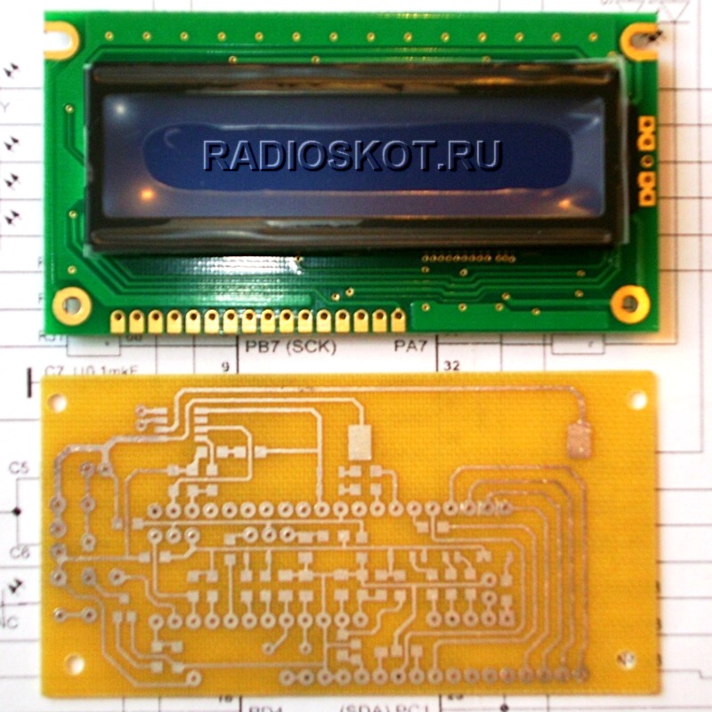
Fig.1. Front side of the device

Fig.2. Rear side of the device
The volume increase is carried out by the button or remotely from the remote control ( infrared control). Suitable for almost any home remote control.
The device diagram is shown in Figure 3.

Fig.3. Schematic diagram
Audio level switching is based on the CD4017 decimal counter (DD1). This chip has 10 outputs Q0-Q9. After power is applied to the circuit, a logical unit is immediately present at the output Q0, the HL1 LED is lit, indicating a zero sound level. Resistors R4-R12 are connected to the remaining outputs Q1-Q9, which have different resistances.
Let me remind you that the microcircuit at the same time gives a signal high level only on one of its outputs, and sequential switching between them occurs when a short pulse is applied to the input (pin 14).
Based on this, the resistances in the group of resistors R4-R12 are selected in descending order (from top to bottom according to the diagram), so that with each switching of the microcircuit, more and more current flows to the base of the transistor VT2, gradually opening the transistor.
The collector of this transistor receives a signal from an external ULF or sound source.
So, by switching the counter chip, we, in fact, change the collector-emitter resistance and thereby change the volume of the sound coming to the speaker.
The resistance of the resistors depends on the gain of the transistor (h21e). For example, when using 2N3904, the resistance of the resistor R4 can be about 3 kOhm in order to “open” the transistor a little, the sound will be at the quietest level. And the resistance R12 should be the smallest of the entire group (about 50 ohms) in order to ensure saturation mode and maximum throughput collector-emitter, respectively, the maximum volume of this regulator.
It is difficult for me to specify the specific ratings of R4-R12, since this is still very much dependent on the power of the audio signal applied to the transistor, as well as on the power supply. It is best to use multi-turn trimmers and adjust the stages "by ear".
The lower part of the diagram shows an indication unit based on the K176ID2 (DD2) decoder. It is designed to control a seven-segment indicator.
A binary code is supplied to the decoder inputs, therefore, an encoder is built on the VD1-VD15 diodes, which converts the decimal signal from CD4017 into a binary code understandable for K176ID2. Such a diode circuit may seem strange and archaic, but it is quite efficient. Diodes should be selected with a low voltage drop, such as Schottky diodes. But in my case, ordinary silicon 1N4001 were used, they can be seen in Figure 2.
So, the signal from the output of the counter goes not only to the base of the transistor, but also to the diode converter, turning into a binary code. Next, DD2 will accept a binary code and the desired number will be displayed on the seven-segment indicator, showing the sound level.
The K176ID2 chip is convenient in that it allows the use of indicators with both a common cathode and a common anode. The scheme uses the second type. Resistor R17 limits the segment current.
Resistors R13-R16 pull the decoder inputs to minus for stable operation.
Now consider the upper left part of the diagram. DIP switch SA1 sets the volume control mode. In the upper (according to the scheme) position of the SA1 key, the volume is changed manually by pressing the tact button SB1. Capacitor C3 eliminates contact bounce. Resistor R2 pulls the CLK input to minus, preventing false positives.
After power is applied, the HL1 LED lights up, and the indicator shows zero - this is the silent mode (Figure 4, top).

Fig.4. Displaying levels on the indicator
By pressing the tact button, the volume of the speaker increases in small jumps from the 1st to the 9th level, the next press again activates the silent mode.
If you set the switch to the lower (according to the diagram) position, then the input DD1 is connected to the infrared remote control circuit based on the TSOP receiver. When an external IR signal arrives at the TSOP receiver, a negative voltage appears at its output, which unlocks the transistor VT1. This transistor is any low-power, PNP structure, for example, KT361 or 2N3906.
I recommend choosing an IR receiver (IF1) with an operating frequency of 36 kHz, since it is at this frequency that most remotes (from a TV, DVD, etc.) operate. Pressing any button on the remote control will control the volume.
In the circuit there is a button with fixation SB2. While it is pressed, the reset pin RST is connected to the minus of the power supply and the counter will be switched. With this button, you can reset the counter and the volume level to zero, and if you leave it in the off position, the reset pin will not be pulled to minus and the counter not will receive signals from the remote control, and not will respond to pressing the SB1 button.

Fig.5. Switches, tact button and TSOP receiver with binding are brought to a separate board
I feed the audio signal to the regulator transistor from the amplifier on the PAM8403 chip. The VT2 collector is connected to the positive output of one of the amplifier channels (R), and its emitter is connected to the positive speaker terminal (red wire in the photo). The negative contact of the column (black-red) is connected to the minus of the channel used. The sound source in my case is a mini mp3 player.

Fig.6. Device connection
Why are trimmer resistors used?
I want to draw your attention to the photo of the back side of the device (Fig. 2). It can be seen that there are three tuning resistors R4, R5, R6 for 100 kOhm. I implemented only three volume levels, because the rest of the resistors (R7-R12) did not fit on the board. Trimmer resistors allow you to adjust the volume levels for different sound sources, because. they differ in audio signal strength.
Device flaws.
1) Volume control only occurs up the level, i.e. only louder. It won’t work right away, you will have to reach the 9th level and then return to the initial level again.
2) The sound quality is slightly degraded. The greatest distortion is present at quiet levels.
3) Does not control the stereo signal. The introduction of a second transistor for another channel does not solve the problem, because The emitters of both transistors are connected to negative power, resulting in a "mono" sound.
Schema improvement.
You can use a resistor optocoupler instead of a transistor. A fragment of the circuit is shown in Figure 7.

Fig.7. A fragment of the same circuit with an optocoupler
A resistor optocoupler consists of an emitter and a light receiver connected optical communication. They are galvanically isolated, which means that the control circuit should not interfere with sound signal passing through the photoresistor. The photoresistor under the action of the emitter light (LED or the like) will change its resistance and the volume will change. The elements of the optocoupler are galvanically isolated, which means that two or more channels of the audio signal can be controlled (Fig. 8).

Fig.8. Two-channel control with resistor optocouplers
Resistors R4-R12 are selected individually.
The device can be powered from USB 5 volts. When increasing the voltage, increase the resistance of the current-limiting resistor R17 so that the seven-segment indicator HG1 does not fail, and also increase the resistance R1 to protect the TSOP receiver. But I do not recommend exceeding the supply voltage above 7 volts.
This article has a video that describes the principle of operation, shows the design assembled on the board and conducted a test this device.
List of radio elements
| Designation | A type | Denomination | Quantity | Note | Score | My notepad | |
|---|---|---|---|---|---|---|---|
| Components for the circuit (Fig. 1) | |||||||
| DD1 | Special logic | CD4017B | 1 | Decimal counter | To notepad | ||
| DD2 | Chip. Decoder | K176ID2 | 1 | To notepad | |||
| VT1 | bipolar transistor | 2N3906 | 1 | Any low power PNP | To notepad | ||
| VT2 | bipolar transistor | 2N3904 | 1 | Can KT3102 | To notepad | ||
| VD1-VD15 | Schottky diode | 1N5817 | 15 | To notepad | |||
| C1 | 47 - 100uF | 1 | To notepad | ||||
| C2 | Capacitor ceramic | 0.1uF | 1 | To notepad | |||
| C3 | electrolytic capacitor | 1 - 10 uF | 1 | To notepad | |||
| R1 | Resistor | 100 ohm | 1 | To notepad | |||
| R2 | Resistor | 20 - 100 kOhm | 1 | To notepad | |||
| R3 | Resistor | 100 - 300 Ohm | 1 | To notepad | |||
| R4-R12 | Resistor | Pick up | 9 | Pick up | |||
With the development and improvement of microcircuits for audio amplifiers (both pre- and final), there is a desire to upgrade and control. And it is best to use the controller for this. I was very interested in this project in terms of functionality, the author of the regulator circuit and the firmware itself made a lot of efforts to bring the control program to perfection (many thanks to him for that!). Further I copy the description of the author with small reductions.
Schematic diagram of the main unit
microcontroller controlled preamplifier Atmega16 built on a modular principle, that is, individual modules can be performed by everyone according to their wishes and preferences. This is especially true for output power amplifiers, power supplies, protection acoustic systems. In this material, we will consider the input module on the chip TDA7313 and processor control unit. Chip TDA7313 included by standard scheme and has no features. The unit is powered by a +9 volt power supply. This block has no other features. PCB files of this and other modules archived on the forum, there is circuit diagrams to connect the keyboard, final amplifier and power supply.
Main parameters of the module:
1. Volume control (16 levels);
2. Gain control (4 levels);
3. Bass tone control (16 levels);
4. Treble tone control (16 levels);
5. Front speaker balance adjustment (16 levels);
6. Rear speaker balance adjustment (16 levels);
7. LOUDNESS - On / off subtlety;
8. MUTE mode;
9. STANDBY mode;
10. Time display mode MUTE and STANDBY as well as after 10 seconds, when there were no keystrokes and other control actions;
11. Control of all functions from the keyboard, remote control (RC) The remote control works according to the RC-5 standard, as one of the most common;
12. Management using Valkodera (encoder);
13. Temperature control of radiators or internal temperature in the case via two channels based on sensors from DALLAS DS18x20. When the set control temperature is exceeded, the cooling fan turns on.
The module mainly uses SMD elements. Chips in DIP packages. Diode VD10 is installed on the opposite side of the board. The amplifier is controlled using the keyboard, the encoder and the remote control. You can use any remote control that works according to the standard. The keyboard is built in the form of a matrix of 12 buttons (4x3):
INPUT1- choice of 1 channel;
INPUT2- choice of 2 channels;
INPUT3- choice of 3 channels;
LOUDNESS- switching on/off the mode of loudness;
MUTE- turn off the sound (switching off occurs smoothly, not abruptly). Pressing again turns on the sound;
STANDBY- turn off the amplifier. The power amplifier and its power supply are turned off, the processor module is in standby mode;
MENU- a button to enter the additional menu, in which you can set additional parameters, such as time, date, temperature of operation of temperature sensors for monitoring radiators. Pressing this button again in this mode returns to the main amplifier control menu without saving the parameters. To save the new settings, click on the button SET.
SET- as mentioned above, this is saving the entered new parameters in the submenu. In the main when pressing a key SET you can see the temperature of the radiators, the information is displayed within 3 seconds.
UP/DOWN- move to the previous/next menu item or submenu;
LEFT/RIGHT- decrease/increase of the corresponding parameter, which is displayed on the indicator.
The main buttons are processed by the program almost instantly, but pressing and responding to the button STANDBY required to be pressed for approximately 3 seconds. Buttons MUTE and LOUDNESS about 1 second. This is done to avoid triggering accidentally pressed these buttons, especially when using the remote control. The main menu of the amplifier control program consists of the following items:
Volume(Volume)
Attens(Gain)
Bass(Voice Bass)
Treble(Treble tone)
Balance F(Front speaker balance)
Balances R(Rear speaker balance)
The key also works in this mode. SET, when pressed for 3 seconds, the temperature values from the sensors are displayed. By pressing the button MENU we will get to an additional menu for setting the time, date and maximum temperature parameters for the temperature protection to operate. This menu consists of the following items:
"Set Time: Hour" (time setting - hours),
"Set Time: Min" (time setting - minutes),
"Set Time: Sec" (time setting - seconds),
"Set Date: Day"(set date - day),
"Set Date: Mes" (set date - month),
"Set Date: Year"(set date - year),
"Set MAX DS18x20" (setting the temperature of the thermal protection operation).
In this mode, navigation through the menu is carried out with the keys UP/DOWN(and remote control keys), and adjusting the parameter with the keys LEFT/RIGHT(and the encoder). In any of the paragraphs, if we press the key MENU, then we will return to the main menu without writing new values, and if we press the key SET, then with saving the entered parameters. For convenience, the author provided firmware in English, Russian and Ukrainian. As an option, for myself I decided to control only the remote control, so I don’t want to assemble and install the valcoder and keyboard. The payment that the author brought was made for himself, so he decided to breed his own.
I finished assembling the preamplifier - everything opens and is regulated. Since there are no sensors, they are not defined either (in the form of dashes in standby mode). I wired my board for SMD, but the processor is in a Dip package, so the board for it is the size of the indicator - this is the main reason why I don’t lay out the board in Lay.
The second payment will be preamplifier on TDA7313. The third board is the power supply control module and standby mode. Here is a photo:
It's time for testing. Plays great! We are pleased with the depth of bass and treble adjustment, the bass is soft, the tweeters are high up to the “chime” (although it will be more fun with OM, of course), loudness was especially liked by the very impressive rise to the bass. In general, for the device, so far I can only say one thing - solid pluses!
Having driven for half a day, I did not find any flaws in the firmware, the work on the remote control is clear, in general, if anyone decides to repeat this scheme, he will not regret it! Schematic author - Andrey Doinikov. Assembly and testing - GOVERNOR.
Discuss the article MICROCONTROLLER CONTROL IN ULF
The motorized potentiometer is not new for a long time, there are even ready-made devices for sale. The price for it can be said to be "space" and not affordable for many radio amateurs, like me! 🙂
The idea itself is very interesting, because such a connection has many advantages - no interference from adjustments is introduced into the sound, it can be easily connected to the remote control, for remote control, the device itself can be used anywhere, replacing it with a conventional potentiometer!
But besides the pluses, there are also minuses - For a direct connection of the potentiometer with the shaft, only a stepper motor is suitable, for a regular one you need a gearbox! During the adjustment, the sound of the motor will be heard, the motor must be controlled ...
However, with these disadvantages, there are still many benefits from this type of regulator, and I will tell you how I implemented it!
It all started with the fact that I had accumulated a lot of different motors, stepper and conventional:
I had to adapt them somewhere)) I didn’t touch the steppers, I will need them for other purposes, but I decided to twist the usual ones with a potentiometer to adjust the volume, since I had long wanted to adjust the volume with the remote control, for example, listening to the radio at work or watching a movie on the computer.. 🙂
Connecting the motor directly to the potentiometer will not work, the motor may not have enough strength to rotate the potentiometer shaft, or vice versa, the motor will have so much dope that it will turn the shaft completely in a split second! =)
For this I needed a gearbox! But it was difficult to make a gearbox on my own, I didn’t have materials ... Then fantasy went into battle ...
I went to a flea market, bought a cheap Chinese inertial machine for 10 hryvnias, removed a very necessary part from it and tried to connect it with a potentiometer:

As you can see, the motor was “embedded” in the very place where the inertial shaft stood, I removed the gear from it and put it on the motor axis, such a simple design came out!
The first tests were great! The motor exactly turned the handle of the resistor, but it still rotated it relatively quickly ... Then I needed a control circuit, but more on that later ...
Then I bit off the unnecessary parts of the axis of such a gearbox with wire cutters and with the help of a needle file I grinded off one part “for a screwdriver”:

The mount turned out to be very strong, the Chinese did not save on the material for the axis))
Actually what happened in the end:


The dimensions came out relatively small ... I fixed the gearbox on a piece of textolite with hot glue (a cool thing, by the way, very useful for household chores) and simply soldered the potentiometer with the case to the textolite!
Then I took up the motor control circuit ... I needed an indication of the volume level, since the device would be inside the case, you need to see what position the regulator is in, it would not be very good to turn on the amplifier at maximum volume at night! 🙂
Here's the schematic that came out:

The option is of course “raw”, but in practice everything works very well!
Briefly describe how IT works:
A twelve-step indicator is assembled on transistors, which performs two functions - a volume level indicator (when the volume key is not pressed) and a display of the volume status for a couple of seconds after pressing the key louder or quieter and switching back to the level indication mode!
The motor control circuit itself is assembled on the “555” timer, which generates pulses to control the motor, communication with the motor occurs using the “H” bridge, assembled on powerful transistors (which I used and used, but I only had TIP100 and TIP106) . Transistors in the bridge which I used:

The driver always generates pulses, but in order to choose which direction to rotate the motor, we need to close one of the pairs of transistors by applying one to any of the inputs (L or R)! If you hook up an IR receiver to these inputs, as, for example, from an article about the past "Amplifier with Remote Control", then the volume can be adjusted with any remote control! I additionally put two buttons on the case, well, it’s not always possible to operate the remote control! 🙂
It may be necessary to use an additional amplifier for the level indicator input (LINE IN input), since on the mp3 player it did not have enough volume even at the maximum to show the level, but from the computer it worked at full ...
Also on the diagram there is an approximate drawing of how this system is connected!
As far as I assembled the circuit from scratch, I decided at first to do everything with a body kit ... This is how my “H” bridge and the whole device looked like:


It's scary, of course, I do not argue, but it works =))))
Later I made a printed circuit board for it, which I posted on the forum ... I say right away - I did NOT check it, I did it on hastily and there may be errors in it! I would be grateful to anyone who checks it! 🙂
Despite the terrible appearance, the device works very well, smoothly adjusts the volume, and in combination with the remote control, it turned out very conveniently!
And finally, here's the video:
On the video, it may seem that the volume is adjusted sharply, this is due to the fact that I connected the test amplifier (on the TDA8563) directly through the potentiometer to the computer! When connected via a tone block, the adjustment is much smoother!
First, the video shows an indication of the volume status, I close the “Louder” contact and the indication switches to the volume level mode, the LED strip fills up, after a couple of seconds when I release the contact, the indication returns to the signal level display mode (VU Meter). I turn on the amplifier, give a signal ... For tests, I used an amp on the TDA8563 and a car speaker, which turned everything on my table with vibration! 🙂
Organization volume control in high-quality equipment has always been an important and not simple issue. The potentiometer used for this must have a high channel identity (for paired potentiometers), good wear resistance, no extraneous sounds(rustles and crackles) when adjusting. Today, conventional variable resistors are being replaced by hardwire switches, relay circuits, or integrated circuits. With significant cost and complexity, such options, solving some problems, give rise to others. Therefore, many lovers quality sound still prefer "old-fashioned" potentiometers.
If you set out to find a high-quality potentiometer for your amplifier, you will definitely and quickly come across the company's products. ALPS. Indeed, their products are used in expensive devices and have high performance at a reasonable price. ALPS produces both conventional and motorized potentiometers. It is the latter that allow you to adjust the volume using remote control. You just need to connect the control circuit.
This article presents a circuit that allows you to remotely control motorized potentiometers. ALPS, as well as switch the amplifier's five inputs using a standard RC-5 remote control.
One microchip.
Apart from the supply voltage stabilizer, the circuit contains only one microcircuit - this is the Atmel ATmega microcontroller, which is responsible for decoding RC-5 signals, generating signals for motor control and input switch relay control signals.
Schematic diagram of the device is shown in the figure:

zoom on click
The scheme is quite simple and does not require detailed explanations. Let's just focus on some important points.
Ports PD2-PD6 via connector K3 can be used to control the relay of the preamplifier input switcher.
The pins of the PC and PB ports are connected in parallel to increase the output current. They are used to control the potentiometer drive through connector K1. The maximum motor current according to the ALPS documentation is 150 mA. The maximum current of the microcontroller port according to the Atmel documentation is about 40 mA. By paralleling 6 outputs, we can get a control current of more than 200 mA.
To indicate the rotation of the engine, LED D1 is connected in parallel with it. Here it is necessary to use a two-color LED and by the color of the glow it will be clear in which direction the engine rotates. If desired, it can be displayed on the front panel of the amplifier.
The structure can be powered from a separate transformer, which is connected to the K5 connector. Or constant voltage from the power supply of the amplifier itself. In this case, voltage is supplied to the board through connector K4, and elements B1 and C10-C13 can be omitted.
Design.
The figure shows the arrangement of elements on the printed circuit boards of the device:

The design is divided into two parts for ease of placement in the amplifier case. The motorized potentiometer itself is located on one board. This board is mounted in close proximity to the front panel of the amplifier.
The second board contains the power supply, microcontroller and other elements of the device. It is desirable to place this board in the amplifier case as far as possible from the audio circuits and, if possible, shield it to reduce radiated interference.
The IR signal receiver must also be placed on the front panel of the amplifier by connecting it to the board with a three-wire cable. With a long cable length, in order to exclude unstable and false alarms of the receiver, it is necessary to duplicate the capacitors C2 and C3 by soldering them directly at the receiver's terminals.
All connections of the structure are implemented by connectors, which are interconnected by loops with the appropriate number of cores.
On the printed circuit board potentiometer, contacts are provided for connecting the shield of the signal cable and the shield of the motor control cable, if necessary.
A photo of the finished structure is shown in the figure:

zoom on click
Signals for transistor switches control relays of the input switch are removed from connector K3. To switch inputs on the remote control, use the number buttons 1...5. In this way, the desired input can be directly selected. To switch inputs sequentially on the remote control, use the up / down channel switching buttons.
Important note.
The author tested his development with a remote control from Philips devices. It is clear that not every home has products of this well-known brand, so attempts have been made to check the compatibility of other remotes. The universal remote control "EuroSky 8" turned up under the arm (in the photo it is black on the right):

This remote worked well. various devices in the house, but when it was programmed to work with audio devices, errors were observed when working out auxiliary functions. It turned out that some remotes do not work correctly with the RC-5 standard.
The editors of the magazine "Elector" carried out modernization software this unit in order to minimize errors when working with various remote controls different manufacturers. The tests carried out with the Philips SBC RU 865 universal remote control showed excellent performance. With others universal remotes DU shouldn't be a problem either.
If you have a remote control tester, you can check if your remote control complies with the RC5 standard using the table below:

Here, for example, incorrect codes are presented, which were transmitted by the "EuroSky 8" remote control. The right column shows the correct command codes.
The article was prepared based on the materials of the Elector magazine.
Successful creativity!
Editor-in-Chief of the Radio Newspaper.