How to disassemble a phone charger. How to test a car battery charger
How take apart telephone Sony Ericsson W595
We disassemble the Sony Ericsson W595 phone to change the matrix.

Warning
This article is not a guide to action! You are solely responsible for the collection and disassembly of your device.
Many manufacturers do not bear warranty obligations if the device has been disassembled by the user. If you do not want to lose the warranty for your device, check the terms of warranty obligations in the documentation or with the device manufacturer.
Tools Used

Now you can remove back panel phone case. To do this, stick a tool for parsing cases (or a credit card) into the gap between the grayish panel and the battery compartment, and run it along the perimeter of the case to separate the latches.

It should turn out like this. Two small pieces will fall out on their own when you remove the back panel. Then remove the two self-tapping screws marked with circles.

Now you can remove the battery compartment, before that, peel off the cable glued on the side. After you remove the battery compartment, remove the two circled screws.

Raise motherboard up. It is still connected by a loop. Pull on the dark tab on the connector to pull it out of the connector.

It should turn out like this.

Assembly is done in reverse order.
Similar articles
You can rate this article:
welcome (already left 35 comments)
Thank you so much for the annotation on disassembly. For my mother, this phone was washed in the wash by chance. machine more than one year ago. We took it out, blew it with a hair dryer - I didn’t get it. They gave us a repair and they told us that everything was useless. I'm on this moment I found it by chance, I generally forgot about it earlier in the evening. Decided to try take apart and seriously dry all the circuits)) With the help of your website, I took it apart, dried all the circuits with a hot hairdryer, where there were traces of oxidation and water, smeared all the circuits with salicylic acid (alcohol 1%), dried it again, put it back together. I really wanted to make it work) And here is a festive moment, I press the button, ... ЁЁЁЁЁЁЁЁ. turned on. URAAA. I almost screamed with joy at all, it's impossible - 23:05 already))) Super)) Thank you for you!
How to disassemble a glued power supply
How to disassemble glued power supply from the router is neat and safe. .
How to Disassemble ASUS Charger The Right Way USB Repair
The best method for disassembling a glued Charger is shown. Disassembly without damage and do-it-yourself repair
Maxim, cool! Thanks for the comment 🙂
The article is amazing, a huge thank you for you, Roman! 😉
I have a discrepancy in the “0” button, I thought - the contacts under the button were oxidized / clogged, I looked - everything is clean. 🙁 I wiped it with alcohol - it does not work. But I found something else, if you press on the area a little to the left and above “0” and immediately press on “0”, then everything works. Now I don’t know, I need to somehow crawl under the keyboard - maybe I’ll see something there. 🙁
Yes, apparently - a small resistor, if it is he - soldered off. Just from that row of small parts a little above and to the left of "zero". Such are the things.
Cyril, if you really soldered off, you can solder it. But did he really screw up? Maybe just a problem with the Claudia substrate?
Exactly, exactly! 🙂 It even falls off on one side in the truest sense of the word. Therefore, for now, just glued the adhesive tape on top, it holds, but in order for the button to work, you still need to press it. Solder until there is no ability, I will endure.
Hm, curious, but if you remove it altogether and connect the contacts directly? Why is he needed there at all?
My comment here is the very first. So, please tell me why I dried all the microcircuits, the phone turned on, but the keyboard (1,2,3,4,5,6,7,8,9,0,)
Thank you, now I figured out how to disassemble! I have a problem, in the process of charging the phone, the child spilled tea and got into the area of \u200b\u200bthe charging plug, now the charge is not going on, I tried to measure the voltage at the phone terminals without a battery, there is not even 3 volts, the battery was zero for a day
Doesn't turn on telephone.Pitana have what to do?
The phone does not turn on, how to find the reason?
Alexey, Alexander, Meruert better take the phones to a good service.
I downloaded new songs, when they were played, the phone turned off. It began to turn on, showed the logo, then a black screen and periodically vibrates, what should I do?
Alena, reflash telephone.
I have such a problem, I started issuing contacts without names with squares, zeros, I rebooted it, it reaches the Sony Ericsson logo and that's it, it doesn't go any further, it doesn't react to anything! I went to the workshop, they say that everything cannot be done. What do you advise? Thank you!.
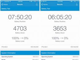
The voltage on the battery was about 3.1 volts, which is less than the threshold after which some chargers recognize the battery and begin to charge it. Anyway, that's how it was with my Blackberry battery, which went too deep.

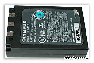
The LI-12B battery was brought back to life by charging with a small current, about 100 mA. For this, it was collected simple circuit. When the voltage on the battery reached 4.2 volts, I stopped the charge and checked the camera's performance. The camera started working and I began to think about how to repair the charger. https://website/
Repair charger LI-10C.

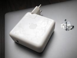
This is what it looked like when I got it Charger.

To disassemble the LI-10C charger, it was necessary to unscrew two self-tapping screws, one of which was under the sticker.
Checking the operation of the charger revealed the presence of short-circuited turns in isolating transformer impulse block nutrition.

The pulse transformer turned out to be unrepairable, besides, I did not find a suitable ferrite core so that I could wind a new transformer.
The picture shows the printed circuit board of the charger. The arrow marks the transformer DS-4207 KT04044.

I decided it was already time to go to our radio market after the weekend, but then I remembered that I have a five-volt charging board for a mobile phone.

I once bought this charger in a faulty condition for the sake of a plug case, so that a power supply for a radiotelephone, once designed for mains voltage 120 volts.

To check the transformer, I had to first draw a diagram, and then replace all the burnt parts.
To my joy, the transformer turned out to be good, and it seemed to be just right in terms of dimensions.
Actually, all further repairs consisted in replacing the transformer.
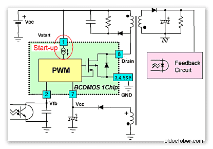
If you look at typical scheme turning on the PWM driver chip of this FSDH0165 charger, you can see that the transformer from the circuit above is functionally not much different from the burnt one.
Good evening, dear blog readers! For a long time, I had a charge for my LG phone, which actually charged a bunch of other devices for me. But at one fine moment, I noticed that the phone was not charging as expected. Either the phone is charging, or not, the charging status could change once a second. I put it aside for a long time, bought new charger, but still the question of how to fix the charger for the phone arose and itched))).
Charging for the phone was composite - a usb wire was inserted into the plug, which in turn was stuck into the phone. There could be two reasons for the failure of charging here:
- broken usb cable
- a fault in the fork itself
The first option is easy to check - just replace the wire itself, I’ll say right away that it didn’t help, otherwise it would probably not make sense to write a whole article about it.
There was a malfunction in the fork ...

In order to find a malfunction and eliminate it, it was necessary to open such a plug. On top it is crowned with a gray plastic mask, which is well glued to the white body of this fork. Of course, if my task were not to fix the Just for fun charger, but to save it for future generations of further use, then I would be very confused. But I barbarously broke off the gray top and took out the internal board with pliers.


Quite an ordinary handkerchief from the phone's usb-charging. The low-voltage part, the PWM environment and the part where the contacts for connecting to 220 V with a diode bridge and resistance are located separately.
Because charging periodically still worked, the logic suggested that the contacts in the plug itself were just leaving. Pay attention to these contacts:

In turn, in the plastic case, where the plug pins are attached, there are also contacts:

Cleaning them, slightly raising them, and also wiping the contacts on the side of the board with an eraser solved the problem - after assembly, the charging worked as it should.
If the below cosmetic steps did not help, then we would have to dig deeper. I had to check again if the capacitor was swollen, so large, located next to the 220 V contacts on the board. It would also be necessary to "inspect" the input resistance, which plays the role of a fuse (the green thing with stripes in the photo above). Judging by my measurements with a multimeter and by the markings on the "belly" of the resistance, its value in this charge was 10 ohms. If it burned out, it would need to be resoldered, but this would indicate a problem in the circuit. That is, it would be masking the problem.
Also, one of the problem areas in charging is the transistor, it often burns out.
In the process of working on this post, I needed to edit a video, which I, however, did not upload. If there is a need to cut video, insert simple titles, then there is not much point in resorting to some paid products, everything is already in Windows - this is Windows Movie Maker. But as soon as it is necessary to do something more, for example, to enlarge the video, then this program is no longer enough. I liked the program, which combines a number of useful qualities - it is quite powerful, easy to learn and cheap. I appreciated it and even acquired. It easily allows you to apply special effects, hide on the video what is somehow reluctant to show (wallet numbers, phones, etc.), stabilize the video and a whole lot more. I'll do a short review of it later.
Subscribe to blog updates!
Thanks to! You have successfully subscribed to new blog posts!
Now, more than ever, the number of gadgets per person has reached its maximum value.
Phones, tablets, laptops, miscellaneous wireless headsets- all this abundance of equipment has a power source and, accordingly, a charger for it.
The phone does not charge from the charger - what to do?
Often they carry charges with them in a bag or pocket, and so that they take up a minimum of space, their cords are twisted with a kink and a stretch.
This, in turn, leads to a wire breakage that is almost imperceptible to the eye and charging inoperability. Just break in cord- this is the most common failure in these types of devices, and, frankly, it is a pity to throw it away because of this.
Yes, you can, of course, buy a new one and not suffer, but if the device is non-standard, for example, an old model phone, then it is not always possible to find such a charger. And at the "flea market" you can slip a block with the same problem, and no one needs extra spending.
Therefore, repairing the charger is a useful and worthwhile business.
How to fix a charger for a phone, smartphone, tablet with your own hands
Below, this article will describe a simple and no-requiring special equipment repair method that will give your charger a second life.
In the photo - charging with a problem in the cord.
It is not always visible to the naked eye. It can hide under the thickness of the main (top) insulation and remains almost invisible.
But, as practice shows, a fracture occurs most often near the entrance to the block or at the base of the plug.
To find the place of the break, just connect the included charger to the phone and move the cord in a suspicious place.
As soon as you see that the charge has “started” for a moment, then there is a break in the place where you were moving at that moment.
In this case, after looking closely, the kink and break were visible even without stirring. It just turned out at the entrance to the power supply.

The main problem in the repair of such blocks is that it is not collapsible. So to get to electronic board, you need to show accuracy and some effort.
Using a screwdriver and a knife, you need to pry the base of the back cover and remove it.

Pry off at the point where the cord enters the device. If the entrance is too tight, you can cut the rubber band slightly.

This must be done carefully so as not to cut the wire at all.
Podkovyrnuv screwdriver, trying to lift the cover up.

It may happen that it will crack in half, but more often, as in this case, the cover came off completely, without damage.

It was even seen that it has latches, and in the case of the charger there are recesses for them.
This means that it is possible to put the cover back into place after repair without using glue.
When the cover is removed, you need to pull the printed circuit board out of the case. Since it "sits" tightly, a screwdriver will help to get it. Having rested the screwdriver blade on the case and hooking one of the soldering points with its end, we pull the board out.


The device of the case is such that when the board is inserted inside, its input contacts are connected to the clamps of the power plug pins. Therefore, when installing the board back into the case, you need to take this moment into account.
The photo below shows the board with all its "insides". The wires are soldered on the bottom.

View from the opposite side.

But in the photo there are tracks for input contacts.

The wire will have to be cut below the point where the damage is located. But it is very important to remember which wire is “+” and which is “-”. In some cases, the wires have a matching color, red is the positive and black is the negative.
With color marking, you can safely cut off, and then simply solder the wires, observing the polarity.
In our case, the wires are of the same color, but since the cord is flat, you can trace which side of the cord the wire goes to minus, and which side to plus. Mark, well, and then cut.


Without losing the label, strip and tin the wires on the cord.

Solder them one by one to the board, observing the polarity.


On the printed circuit board at the place of soldering there is usually a polarity marking.

To prevent the cord from dangling at the output, we wind a bandage of black electrical tape around its input. The thickness of the bandage should be such that it enters the slot for the wire and locks into it.


Before installing the cover, check the operation of the device. We turn it on and connect it to the phone. If the phone is not currently with you, use a voltmeter direct current.
Since the internal contact in the socket has a very thin tube, and the probe of the device does not go into it, you can use a piece of thin copper wire to check.

Having inserted it into the tube of the internal contact, we connect the probes to it and the outer terminal of the plug measuring instrument.
The voltmeter shows that voltage is present, which means that the breakdown has been fixed.

Now snap the back cover.

We connect the phone and enjoy the results of the work done.

A mobile phone or other device that uses a charger to charge its battery. The main reasons why the charger may fail are as follows:
Wire break;
Failure of the charger unit;
Violation of the contact connection of the wire with the plug or charger unit.
Very often, the reason for the failure of the charger is a wire break or a violation of the contact of the wire with the structural elements of the charger - the plug and the block. In this case, you can repair the charger yourself. Consider the principle of eliminating damage to the charger wire on a specific example of repairing a mobile charger Nokia phone(with thin plug).
To repair the charger, we need:
Multimeter;
Soldering iron and everything you need for soldering;

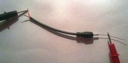
If the device shows a voltage value, then this indicates that the charger unit and the wire are not damaged. In this case, the device showed 7 volts - this is the nominal output voltage this charger. At this stage, we can conclude that the memory does not work due to a violation of the contact of the conductors at the point of their attachment to the plug. You can verify this by ringing the plug with the device.
To do this, which come from the plug, insert a thin wire into the inside of the plug (this is necessary for contact with the inner contact part of the plug).
We take a multimeter and select the dialing mode. With one probe we touch one of the stripped conductors, and with the other, first to the outer contact part of the plug, and then to the inserted wire. If the device showed contact (presence sound signal), this indicates that the contact between this wire and the plug is not broken.


We rearrange the probe of the device to another stripped conductor, with the other we alternately touch the outer part of the plug, and then the wire. If, when touching both contact parts of the plug, the device did not emit a signal, then there is no contact. That is, one of the wires is torn off from the plug.
In this case, there are two ways: you can purchase a new plug, or you can repair the old one. The first way is easier and more reliable. A new plug can be purchased from mobile phone repair shops or the radio market. You may have an old charger with an intact plug.
In this case, it is enough to solder a new plug to the charger, while observing the polarity. How to check the correct connection of wires (polarity)? As a rule, each cord has a . If it does not match, then you need to make sure that the wires are connected correctly.
To do this, plug the charger into a power socket and the new plug into mobile phone. Connect the plug wires to the charger cord. If the charging went, then you connected the conductors correctly. If the phone does not charge, swap the conductors. The check must be carried out in any case, even if the color coding of the connected cords is the same, as there may be discrepancies in the marking of the cords.
The next step is connecting two cords. If you have heat shrink tubing, then before soldering, put a part of it on one of the cords to be soldered. Solder the conductors, observing the polarity. Insulate both wires with insulating tape, put on heat shrink tubing. Check the functionality of the charger.
If you do not have the opportunity to purchase a new plug, but you still want to reanimate the charger, then the second way to repair the damage is suitable for you - repairing the plug.
We remove the rubber (plastic) coating from the plug with a knife. In this case, be careful, do not rush, as you can damage the plug itself.


The next step is to solder the charging cord to the plug.

Check the performance of the charger. If everything is normal, we isolate the conductors, and put a heat shrink tube on the plug. The charger is ready for use.

We considered the case of contact failure at the point of connection of the cord to the plug. There may also be another reason. Let's consider one more case.
You cut the wire, checked for voltage at the output of the charger, it is missing. We cut the wire near the charger, stepping back from the charger unit 7-10 cm. We clean the wire that comes out of the charger unit and check for voltage at the output. The presence of voltage at the output indicates that the memory is working properly. We call the plug according to the above method. In this case, there is no contact failure.
The continuity of the charging cord showed that one of the conductors was broken. No visual damage is visible. The best option is to purchase a new wire. Then solder it to the plug and charger unit, observing the polarity.
In order not to be mistaken (especially if the wires have the same color coding) before soldering the wires, connect them and plug the charger plug into the phone. If charging has started, connect the conductors by soldering. Insulate the wires at the soldering point and put on a heat shrink tube (it must be put on the wire before soldering). The damage has been repaired.
If the wire is intact, the contact connection of the plug is not broken, then the charger unit is damaged or one of the wires inside the unit is torn off.
Unscrew the charger block and look at the wire connections. If all the wires are connected normally, then the memory unit itself is damaged.
If your charger unit is damaged, then, without having skills in the field of electrical engineering, you will not be able to find the cause of its failure, much less fix it yourself. Repairing a charger at a specialized service will cost you more than a new charger.