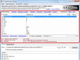
Measuring devices that are at home. Measure everything! Measuring instruments in the kitchen and at home
The general purpose of measuring instruments is to control the norms that are acceptable for health. They are usually very easy to use.
It can be:
- indicators of purity, which determines the tds meter;
- temperature level - it can be found using a pyrometer;
- the amount of light, the indicator of which is important for photographers and printers, is found using a luxmeter, etc.
We can say that all such devices are in demand, but not at hand. The reason is that until the need arises, few people think of getting mini-equipment for measuring. But if in the case of a luxmeter it is quite natural that the photographer will notice its obvious need, then the same TDS meters may remain on the list of unrecognized ones, although they are vital.

Clean water is the key to health
There are several reasons for buying a TDS meter, since the scope of such a meter is to determine the level of water purity. By purchasing a water filter, many calm down, believing that now they get clean and harmless water. This is self-deception. Today, boiler houses supply water so polluted with all sorts of impurities that one treatment may not be enough for it. In addition, cartridges purify water as much as possible according to their capabilities only in the initial period of operation.
Subsequently, water can still pass through clogged filters, but there will be no question of any cleaning. The presence in the house of a device that controls the operation of filters will positively affect the health of all family members.

As you know, water is a necessary product, the consumption of which cannot be reduced or eliminated. The presence of unnecessary impurities in the water is dangerous to health, since their intake into the body is regular.
Measuring devices have firmly entered human life. Due to the extensive classification of measuring instruments, it is possible to determine exactly the apparatus that is needed for specific operations. It can be both the simplest, like a tape measure or ammeter, and multifunctional measuring instruments. When choosing a device, you should focus on its purpose and main characteristics.
General information

A measuring device is a device that allows you to get the value of some physical quantity in a given range. The latter is set using the instrument scale. As well as technical devices allow you to translate values into a more understandable form that is available to a specific operator.
Currently, the list of measuring instruments is quite wide, but most of them designed to control the technological process . This can be a temperature or cooling sensor in air conditioners, heating furnaces and other devices with a complex design.
Among the names of measuring instruments, there are both simple and complex, including in design. Moreover, the scope of their application can be both highly specialized and widespread.
To find out more information about a particular tool, it is necessary to consider a certain classification of instrumentation and instrumentation.
Depending on what measuring instruments are, their names may differ in different classifications.

Usually devices can be of the following form:
- Analog measuring instruments and devices in which the output signal is some function of the measured value.
- Digital devices, where the output signal is presented in the appropriate form.
- Devices that directly record the results of measurements taken readings.
- Summing and integrating. The former give readings as the sum of several values, while the latter allow you to integrate the value of the measured value using another parameter.
The above instruments are the most common and are used to measure a number of physical quantities. The complexity of the ongoing physical processes requires the use of several devices assigned to different classes.
Device classification

In different areas, their own classification of devices designed to measure physical quantities is used.
Devices can be divided according to such criteria:
- Conversion method: direct action, comparison, mixed transformation.
- According to the method of issuing information, they are divided into showing and registering.
- The type of output information can be represented by both analog and digital signals.
Recording devices are divided into self-recording and printing varieties. The most progressive option is self-recording devices, since they have a higher accuracy of providing information and more opportunities for measuring previously set parameters.
Analog and digital

Digital control instruments can be either digital or analog. The former are considered more convenient. In them, indicators of force, voltage or current are converted into numbers, then displayed on the screen.
But at the same time, inside each such device there is an analog converter. Often it is a sensor that takes and sends readings in order to convert them into a digital code.
While analog instruments are less accurate, they offer simplicity and better reliability. And also there are varieties of analog instruments and devices that incorporate amplifiers and transducers. For a number of reasons, they are preferred over mechanical devices.
For pressure and current
Everyone from school or university is familiar with such names of measuring instruments as barometers and ammeters. The first are designed to measure atmospheric pressure. There are liquid and mechanical barometers.

Liquid varieties are considered professional due to the complexity of the design and the peculiarities of working with them. Weather stations use barometers filled with mercury. They are the most accurate and reliable, allow you to work under temperature extremes and other circumstances. Mechanical designs are simpler, but digital counterparts are gradually replacing them.
Ammeters are used to measure electric current in amps. The ammeter scale can be graduated both in standard amperes and micro-, milli- and kiloamps. It is best to connect such devices in series. In this case, the resistance decreases, and the accuracy of the measured indicators increases.
locksmith tools

Quite often you can find measuring locksmith tools. Most important characteristic- accuracy of measurements. Due to the fact that metalwork tools are mechanical, it is possible to achieve an accuracy of up to 0.005 or 0.1 mm.
If the measurement error exceeds the allowable threshold, then there will be a violation of the technology of the tool. Then it will be necessary to regrind a low-quality part or replace the entire assembly in the device. Therefore, it is important for a mechanic when fitting a shaft to a bushing not to use a ruler, but tools with greater measurement accuracy.
The most popular instrument with high measurement accuracy is a caliper. But even he will not be able to guarantee an accurate result from the first measurement. Experienced workers take several measurements, which are then converted to some average value.
There are operations that require maximum precision. There are many of these in micromachines and individual parts of large-sized devices. Then you should use a micrometer. With it, you can measure with an accuracy of hundredths of a millimeter. The common misconception that it can measure microns is not entirely true. Yes, and when carrying out standard homework, such accuracy may not be useful, since the current values \u200b\u200bof accuracy and error are sufficient.
Special devices
There is such a well-known device for measuring called goniometer.

Its purpose is to measure the angles of parts, and the design consists of the following elements:
- the device itself has a half-disk with a printed measuring scale;
- the ruler has its own mobile sector, where the vernier scale is applied;
- fixing the movable sector of the ruler is carried out with a locking screw.
The process of measuring with such a device is simple. The detail is applied by one of the faces to the ruler. It must be moved in such a way that a uniform and sufficient clearance is formed between the edges and rulers. Then the sector is fixed with a screw. The indicators are taken first from the ruler, and then from the vernier.
Control and measuring devices have found a fairly wide application in various areas of production, household, plumbing and construction work. They differ both in scope and in the possibility of measurement.
All devices can be subdivided according to the method of conversion, output of information and the type of output information, purpose and other criteria. With a good classification, you can find a specific tool for specific tasks and operations.
A huge selection of diagrams, manuals, instructions and other documentation for different kinds factory-made measuring equipment: multimeters, oscilloscopes, spectrum analyzers, attenuators, generators, R-L-C, frequency response, non-linear distortion, resistance meters, frequency meters, calibrators and many other measuring equipment.
During operation, electrochemical processes constantly occur inside oxide capacitors, destroying the junction of the output with the plates. And because of this, a transient resistance appears, sometimes reaching tens of ohms. The charge and discharge currents cause the area to heat up, further speeding up the destruction process. One more common cause The failure of electrolytic capacitors is the "drying out" of the electrolyte. In order to be able to reject such capacitors, we offer radio amateurs to assemble this simple circuit
Identification and testing of zener diodes is somewhat more difficult than testing diodes, because this requires a voltage source that exceeds the stabilization voltage.
With this homemade set-top box, you can simultaneously observe eight low-frequency or pulse processes on the screen of a single-beam oscilloscope at once. The maximum frequency of input signals must not exceed 1 MHz. In amplitude, the signals should not differ much, at least, there should not be more than a 3-5-fold difference.
The device is designed to test almost all domestic digital integrated circuits. They can check microcircuits of the K155, K158, K131, K133, K531, K533, K555, KR1531, KR1533, K176, K511, K561, K1109 series and many others
In addition to measuring capacitance, this attachment can be used to measure Ustab for zener diodes and test semiconductor devices, transistors, diodes. In addition, you can check high-voltage capacitors for leakage currents, which helped me a lot when setting up a power inverter for one medical device
This frequency meter attachment is used to evaluate and measure inductance in the range of 0.2 µH to 4 H. And if capacitor C1 is excluded from the circuit, then when a coil with a capacitor is connected to the input of the attachment, the output will be resonant frequency. In addition, due to the low value of the voltage on the circuit, it is possible to evaluate the inductance of the coil directly in the circuit, without dismantling, I think many repairmen will appreciate this opportunity.
There are many different schemes of digital thermometers on the Internet, but we chose those that are distinguished by their simplicity, a small number of radio elements and reliability, and you should not be afraid that it is assembled on a microcontroller, because it is very easy to program.
One of the homemade temperature indicator circuits with an LED indicator on the LM35 sensor can be used to visually indicate positive temperatures inside the refrigerator and car engine, as well as water in an aquarium or pool, etc. The indication is made on ten ordinary LEDs connected to a specialized LM3914 microcircuit, which is used to turn on indicators with a linear scale, and that's it. internal resistances its dividers have the same denominations
If you are faced with the question of how to measure the engine speed from washing machine. We'll give you a simple answer. Of course, you can assemble a simple stroboscope, but there is a more competent idea, for example, using a Hall sensor
Two very simple clock circuits on a PIC and AVR microcontroller. The basis of the first circuit microcontroller AVR Attiny2313, and the second PIC16F628A
So, today I want to consider another project on microcontrollers, but also very useful in the daily work of a radio amateur. This is a digital voltmeter on a microcontroller. Its circuit was borrowed from a radio magazine for 2010 and can be easily converted to an ammeter.
This design describes a simple voltmeter with twelve LED indicators. Given measuring device allows you to display the measured voltage in the range of values from 0 to 12 volts in steps of 1 volt, and the measurement error is very low.
A circuit for measuring the inductance of coils and capacitance of capacitors is considered, which is made on only five transistors and, despite its simplicity and accessibility, makes it possible to determine the capacitance and inductance of coils with acceptable accuracy in a wide range. There are four subranges for capacitors and as many as five subranges for coils.

I think most people understand that the sound of the system is largely determined by the different signal levels in its individual sections. By controlling these places, we can evaluate the dynamics of the operation of various functional units of the system: obtain indirect data on the gain, introduced distortions, etc. In addition, the resulting signal is simply not always possible to listen to, and therefore, various kinds of level indicators are used.
In electronic structures and systems, there are malfunctions that occur quite rarely and are very difficult to calculate. The proposed home-made measuring device is used to search for possible contact problems, and also makes it possible to check the condition of cables and individual cores in them.
The basis of this circuit is the AVR ATmega32 microcontroller. LCD display with a resolution of 128 x 64 pixels. The oscilloscope circuit on the microcontroller is extremely simple. But there is one significant disadvantage - it is enough low frequency measured signal, only 5 kHz.
This prefix will greatly facilitate the life of a radio amateur, if he needs to wind a homemade inductor, or to determine unknown coil parameters in any equipment.
We suggest you repeat the electronic part of the scale circuit on a microcontroller with a load cell, firmware and drawing printed circuit board attached to amateur radio development.
Homemade measuring tester has the following Functionality: frequency measurement in the range from 0.1 to 15000000 Hz with the ability to change the measurement time and display the value of the frequency and duration on digital screen. The presence of a generator option with the ability to adjust the frequency over the entire range from 1-100 Hz and display the results. The presence of an oscilloscope option with the ability to visualize the waveform and measure its amplitude value. The function of measuring capacitance, resistance, as well as voltage in oscilloscope mode.
A simple method for measuring the current in electrical circuit is a way to measure the voltage drop across a resistor connected in series with a load. But when current flows through this resistance, unnecessary power is generated on it in the form of heat, so it must be chosen as low as possible, which significantly enhances the useful signal. It should be added that the circuits discussed below make it possible to perfectly measure not only direct, but also pulsed current, albeit with some distortion, determined by the bandwidth of the amplifying components.
The device is used to measure the temperature and relative humidity of the air. The humidity and temperature sensor DHT-11 was taken as the primary converter. A homemade measuring device can be used in warehouse and residential areas to monitor temperature and humidity, provided that it is not required high accuracy measurement results.
Mainly used for temperature measurement temperature sensors. They have different parameters, cost and forms of execution. But they have one big minus, which limits the practice of their use in some places with a high ambient temperature of the measurement object with a temperature above +125 degrees Celsius. In these cases, it is much more advantageous to use thermocouples.
The circuit of the interturn tester and its operation are quite simple and accessible for assembly even by novice electronics engineers. Thanks to this device, it is possible to test almost any transformers, generators, chokes and inductors with a nominal value from 200 μH to 2 H. The indicator is able to determine not only the integrity of the winding under study, but also perfectly detects an interturn circuit, and in addition, it can be used to check p-n junctions for silicon semiconductor diodes.
To measure such an electrical quantity as resistance, a measuring device called an ohmmeter is used. Devices that measure only one resistance are rarely used in amateur radio practice. The majority uses typical multimeters in resistance measurement mode. Within this topic, we will consider a simple circuit An ohmmeter from the Radio magazine and an even simpler one on the Arduino board.
BMK-Miha, most main disadvantage This device is a low resolution - 0.1 Ohm, which cannot be increased purely by software. If not for this shortcoming, the device would be perfect!Original circuit ranges: ESR=0-100Ω, C=0pF-5000µF.
I want to pay special attention to the fact that the device is still in the process of finalizing both software and hardware, but continues to be actively used.
My revisions regarding:
Hardware
0. Removed R4, R5. The resistance of resistors R2, R3 was reduced to 1.13K, and I picked up a pair with an accuracy of one ohm (0.1%). Thus, I increased the test current from 1mA to 2mA, while the non-linearity of the current source decreased (due to the removal of R4, R5), the voltage drop across the capacitor increased, which contributes to an increase in the accuracy of ESR measurement.
And of course Kusil corrected. U5b.
1. Introduced power filters at the input and output of the converter + 5V / -5V (in the photo the scarf is standing vertically and there is a converter with filters)
2. put the ICSP connector
3. introduced the R / C mode switch button (in the "original" the modes were switched by an analog signal coming to RA2, the origin of which is described in the article extremely vaguely ...)
4. Introduced a forced calibration button
5. Introduced a buzzer confirming the pressing of the buttons and giving a signal of inclusion every 2 minutes.
6. Powered the inverters by their parallel pairwise connection (with a test current of 1-2mA it is not necessary, I just dreamed of increasing the measurement current to 10mA, which has not yet been possible)
7. I put a 51 ohm resistor in series with P2 (to avoid short circuit).
8.Vyv. I shunted the contrast adjustment with a 100nf capacitor (I soldered it to the indicator). Without it, when the P7 engine was touched with a screwdriver, the indicator began to consume 300mA! I almost burned the LM2930 along with the indicator!
9. I put a blocking capacitor on the power supply of each MS.
10. adjusted the circuit board.
Software
1. removed the DC mode (most likely I will return it back)
2. Introduced a tabular correction of non-linearity (at R> 10 Ohm).
3. limited the ESR range to 50 ohms (with the original firmware, the device went off scale at 75.6 ohms)
4. added the calibration subroutine
5. wrote support for buttons and buzzer
6. introduced an indication of the battery charge - numbers from 0 to 5 in the last digit of the display.
I did not interfere with the capacitance measurement unit either software or hardware, with the exception of adding a resistor in series with P2.
I have not yet drawn a schematic diagram reflecting all the improvements.
The device was very sensitive to humidity! as you breathe on it, the readings begin to "swim". The reason for this is the high resistance of R19, R18, R25, R22. By the way, can someone explain to me why the hell is the cascade on the U5a such a large input impedance ???
In short, the analog part was filled with varnish - after which the sensitivity completely disappeared.
The magazine ELEKTOR, as far as I know, is German, the authors of the articles are Germans and they publish it in Germany, at least the German version.
m.ix, let's joke in a flame
It deals with the issues of self-manufacturing and operation of measuring instruments used in amateur radio practice.
Homemade amateur radio measuring instruments.
Computer-based home-made and industrial measuring instruments.
Measuring instruments for industrial production.
The updated file archive on the topic "Measuring instruments" is located , over time, I hope to prepare a review with comments.
Functional sweep and tone burst generator.
This article is a report on the work done, carried out at the beginning of the zero years, in those days, independent production measuring instruments and equipment of their laboratories for radio amateurs was considered commonplace. I hope that such enthusiastic and interested craftsmen are found now.
The prototypes for the FGCH under consideration were Nikolai Sukhov's Tone Burst Generator (Radio No. 10 1981 pp. 37 - 40)
and “Attachment to an oscilloscope for observing frequency response” by O. Suchkov (Radio No. 1985 p 24)
Scheme of the prefix O. Suchkov:

Developed on the basis of these sources and other literature (see Notes on the margins of the circuit), the FGCH generates voltages of a sinusoidal, triangular and rectangular (meander) shape, with an amplitude of 0 - 5V with step attenuation of -20, -40, -60 dB in the frequency range of 70 Hz - 80KHz. FGKCh regulators can set any section of the swing or the value of the frequency jump, when forming bursts, within the operating frequency range.
The control and synchronization of frequency tuning is carried out by the increasing sawtooth voltage of the oscilloscope sweep.
FGKCh allows you to quickly evaluate the frequency response, linearity, dynamic range, response to impulse signals and speed of analog radio-electronic devices in the audio range.
The FGCH scheme is presented on drawing.

A high-resolution scheme is located or downloaded by clicking on the picture.
In the sweeping frequency mode, a sawtooth voltage is supplied to the input of the op-amp A4 from the oscilloscope scanner (as in the GKCH circuit of O. Suchkov). If the frequency control input A4 is fed not with a saw, but with a meander, the frequency will jump from low to high. The formation of a meander from a saw is carried out by a conventional Schmitt trigger, on transistors T1 and T2, of different conductivity. From the output of the TSh, the meander enters electronic key A1 K1014KT1, designed to match the voltage level of the control frequency tuning of the FGKCH. A voltage of +15V is applied to the input of the key, from the output of the key, a rectangular signal is fed to the input of the OU A4. Frequency switching occurs in the middle part of the horizontal sweep, synchronously. After the A4 op amp, there are two EPs on transistors T7 - PNP and T8 - NNP (for thermal compensation and equalization of the level shift) In the emitter T7 there is a variable resistor RR1, which sets the lower boundary of the swing or the formation of bursts of pulses in the range 70Hz - 16KHz. Resistor R8 (according to Suchkov) was replaced by two RR2 - 200 KΩ and RR3 - 68 KΩ. RR2 sets the upper limit of the swing range 6.5 - 16.5 kHz, and RR3 - 16.5 - 80 kHz. The integrator on the A7 op amp, the Schmitt trich on the A7 op amp, and the phase switch of the gain of the amplifier A5 - T11, work as described in O. Suchkov.
After the buffer amplifier on the op amp A7, there is a signal shape switch with trimming resistors PR6 - adjusting the level of the triangular signal and PR7 - adjusting the meander level. normalizing the level of output signals. The sinusoidal signal shaper consists of an op-amp A8 - a non-inverting amplifier with gain adjustment in the range of 1 - 3 times (with a tuning resistor PR3) and a classic sawtooth-to-sine voltage converter on a field-effect transistor T12 - KP303E. From the source T12, a sinusoidal signal is fed directly to the pulse shape selector S2, since the level of the sinusoidal signal is determined by the normalizing amplifier on the op-amp A8 and the value of PR3. From the output of the level control RR4, the signal is fed to the buffer amplifier on the powered A9. Buffer amplifier gain about 6, set by a resistor in the circuit feedback OU. On transistors T9b T10 and switches S3, S5, a synchronization unit was assembled, used to check the recording path - playback of a tape recorder, which is currently completely out of date. All op-amps - with PT at the input (K140 UD8 and K544UD2). The supply voltage stabilizer is bipolar +/- 15V, assembled on the OU A2 and A3 - K140UD6 and transistors T3 - KT973, T4 - KT972. Current sources of zener diodes of reference voltage on PT T5, T6 - KP302V.
Work with the considered functional GKCH is carried out as follows.
Switch S1 "Mode" is set to the "Flow" position and the variable resistor RR1 "Flow" sets the lower frequency of the swing range, or a lower frequency of bursts of pulses, in the range of 70Hz - 16KHz. After that, the switch S1 "Mode" is set to the "Ftop" position and the variable resistors RR2 "6-16KHz" and RR3 "16 - 80KHz" set the upper frequency of the swing range, or a higher frequency of bursts of pulses, in the range 16 - 80 kHz. Next, switch S1 is switched to the “Kach” or “Burst” position to form an output voltage of a sweeping frequency or two bursts of pulses of a lower and higher frequency, changing synchronously with the sweep, when the beam passes through the middle of the screen (for bursts of pulses). The shape of the output signal is selected by switch S2. The signal level is regulated smoothly by a variable resistor RR4 and in steps by a switch S4.
The oscillograms of the test signals in the "Sweep" and "Burst" modes are shown in the following figures.


Generator photo assembled, shown in the figure.

In the same case, a broadband sinusoidal voltage generator and a meander (Important: R6 in the circuit of this generator is 560KΩ, not 560Ω, as in the figure, and if instead of R9 you put a pair of 510Kom constant resistor and 100K trimmer, you can, by adjusting the trimmer, set the minimum possible Kg.)
and a frequency meter, the prototype of which is described in.
It is important to note that in addition to checking the analog paths of sound reproducing equipment, in the frequency sweeping and bursting modes, the considered functional GKCh can also be used simply as a function generator. Triangular-shaped signals help to very clearly track the occurrence of clipping in the amplifying cascades, set the signal clipping to be symmetrical (the fight against even harmonics is more noticeable by ear), control the presence of "step" type distortions and evaluate the linearity of the cascade as the front curves and the triangular signal decays.
Even more interesting is the verification of the UMZCH and other sound nodes, with a rectangular signal, with a duty cycle of 2 - a meander. It is believed that for the correct reproduction of a square wave of a certain frequency, it is required that the working (without attenuation) band of the tested cycle be at least ten times greater than the frequency of the test square wave. In turn, the bandwidth of the frequencies reproduced, for example, by the UMZCH determines such an important quality indicator as the intermodulation distortion coefficient, which is so significant for tube UMZCH that it is prudently not measured and not published so as not to disappoint the public.
The following figure is a fragment of the article by Yu. Solntsev "Functional" generator "from the Radio Yearbook.
On the image- typical meander distortions that occur in the audio path, and their interpretation.

Even more visually, measurements using a function generator can be made by applying a signal from its output to the X input of the oscilloscope, directly, and to the Y input through the device under test. In this case, the screen will display amplitude characteristic tested schema. Examples of such measurements are shown in the figure.

You can repeat my version of the functional GKCh, as it is, or take it as an alpha version of your own development, made on a modern element base, with the use of circuit solutions that you consider more progressive or affordable in implementation. In any case, the use of such a multifunctional measuring device will allow you to significantly simplify the tuning of sound-reproducing paths and controllably improve their quality characteristics in the development process. Of course, this is only true if you think that tuning circuits “by ear” is a very dubious technique of amateur radio practice.
Standby mode switcher for S1-73 oscilloscope and other oscilloscopes with Stability control.
Users of Soviet and imported oscilloscopes equipped with a “Stability” sweep mode control encountered the following inconvenience. When a complex signal is received on the screen with stable synchronization, a stable image is maintained as long as the input signal is applied or its level remains sufficiently stable. When the input signal disappears, the sweep can remain in standby mode for an arbitrarily long time, while there is no beam on the screen. To switch the sweep to self-oscillating mode, sometimes it is enough to turn the “Stability” knob a little, and the beam appears on the screen, which is required when linking the horizontal sweep to the graticule on the screen. When measurements are resumed, the image on the screen may “float” until the “Stability” knob restores the standby sweep mode.
Thus, during the measurement process, you have to constantly turn the “Stability” and “Synchronization Level” knobs, which slows down the measurement process and distracts the operator.
The proposed revision of the C1-73 oscilloscope and other similar devices (C1-49, C1-68, etc.) equipped with the “Stability” regulator provides automatic change the output voltage of the variable resistor of the “Stability” regulator, which switches the oscilloscope scanner to self-oscillating mode in the absence of an input clock signal.
The scheme of the automatic switch "Waiting - Auto" for the S1-73 oscilloscope is shown in Figure 1.

Picture 1. Scheme of the automatic switch "Waiting - Auto" for the S1-73 oscilloscope (click to enlarge).
On transistors T1 and T2, a single vibrator is assembled, triggered through capacitor C1 and diode D1 by positive polarity pulses from the output of the pulse shaper for triggering the sweep of the C1-73 oscilloscope (control point 2Gn-3 of block U2-4 in Figure 2)

Figure 2
(completely, the circuit of the C1-73 oscilloscope is here: (Fig5) and (Gif 6)
V original state, in the absence of pulses triggering the sweep, all transistors of the “Waiting - Auto” automaton are closed (see Fig. 1). Diode D7 is open and on the right according to the scheme (see Fig. 2) the output of the variable resistor R8 "Stability", through the circuit R11 D7, is supplied constant pressure, which transfers the sweep generator to self-oscillating mode, at any position of the variable resistor R8 "Stability" slider.
Upon the arrival of the next pulse, the start of the sweep, transistors T2, T1, T3, T4 open in series, and diode D7 closes. From this moment on, the S1-73 oscilloscope's sweep synchronization circuit operates in the typical mode specified by the voltage at the output of the variable resistor R8 (see Fig. 2). In a particular case, a standby sweep mode can be set, which ensures a stable position of the image of the signal under study on the oscilloscope screen.
As noted above, when the next sync pulse arrives, all transistors of the sweep control automat open, which leads to a rapid discharge of the electrolytic capacitor C4 through diode D4, an open transistor T2 and resistor R5. Capacitor C4 is in a discharged state all the time while triggering pulses are received at the input of the single vibrator. At the end of the start pulses, the transistor T2 closes, and the capacitor C4 begins to be charged by the base current of the transistor T3 through the resistor R7 and the diode D5. The charging current of the capacitor C4 keeps transistors T3 and T4 open, keeping the idle sweep mode set by the voltage at the output of the variable resistor R8 "Stability" for several hundred milliseconds, waiting for the next sync pulse. If this does not arrive, the transistor T3 closes completely, the LED D6, which indicates the activation of the standby mode, goes out, the transistor T4 closes, the diode D7 opens and the oscilloscope sweep switches to self-oscillating mode. To ensure an accelerated transition to standby mode, when the first sync pulse in the series arrives, the "Logic OR" element on diodes D3 and D5 is used. When the single vibrator is triggered, leading to the opening of the transistor T2, the transistor T3 opens without delay, along the circuit R7, D3, R5 even before the end of the discharge of the capacitor C4. This can be important if you want to observe single pulses in the idle clock mode.
The assembly of the standby mode machine is made by volumetric installation.

Figure 3. Volumetric mounting of the oscilloscope sleeper.

Figure 4. Element isolation oscilloscope standby machine with paper inserts and molten paraffin.
Before installation, the module is wrapped in a strip of paper taped with transparent tape on at least one side, also to reduce leakage. The side of the paper glued with adhesive tape faces the assembled module. Volumetric assembly of the machine allowed to reduce the assembly time and abandon the development and manufacture of a printed circuit board. In addition, the modules turned out to be quite compact, which is important when they are installed in the small case of the S1-73 oscilloscope. In contrast to pouring a device assembled with a three-dimensional assembly, epoxy compound and other hardening resins, the use of paraffin allows you to maintain the maintainability of the device and the possibility of its refinement, if necessary. In amateur radio practice, with piece production, this can be an important factor in choosing the design of the device.
A view of the standby machine mounted on the U2-4 board, S1-73 oscilloscope, is shown in Figure 5.

Figure 5. Placement of the sleeper module on the timing board of the C1-73 oscilloscope.
The standby LED is located 15 mm to the right of the LEVEL control, as shown in Figure 6.

Figure 6. Placement of the standby indicator on the front panel of the oscilloscopeC1-73.
The operating experience of the S1-73 oscilloscope, equipped with an automatic sweep standby switch, showed a significant increase in measurement efficiency due to the absence of the need to turn the STABILITY knob when setting the sweep line to the desired division of the screen calibration grid and after that, to achieve a stable position of the image on the screen. Now, at the beginning of measurements, it is enough to set the LEVEL and STABILITY controls to a position that provides a stationary image of the signal on the screen, and when the signal is removed from the oscilloscope input, the horizontal sweep line appears automatically, and the next time the signal is applied, a stable picture returns.
You can purchase a similar oscilloscope sleeper to save assembly time. Use the feedback button. :-)
Block of protection and auto-shutdown of the multimeter M830 and similar "Digital Chinese multimeters".
Due to their simplicity, sufficiently high accuracy and low cost, digital multimeters built on the ADC of the family (domestic analogue) are very widely used in amateur radio practice.
Some inconvenience of using the device is associated with:
- The lack of auto-shutdown of the multimeter
- the relative high cost of high-capacity nine-volt batteries
- lack of overvoltage protection (with the exception of a 0.25A fuse)
Various solutions to the above problems have been proposed by radio amateurs in the past. Some of them (protection circuits for the ADC of the multimeter, auto-shutdown, and its power supply from low-voltage power supplies, through a boost converter, are improvements and measuring attachments for multimeters of the M830 family.
I bring to your attention another option for refining the "Chinese digital multimeter" on the ADC 7106, which combines four consumer functions that are important for such devices: Auto-off by timer a few minutes after switching on.
- Overvoltage protection with galvanic disconnection of the UIR input socket from the multimeter circuit.
- Auto power off when protection is triggered.
- Semi-automatic delay of auto-off during long measurements.
To explain the principles of operation and interaction of the nodes of the Chinese multimeter on the IC7106, we use two diagrams.

Fig.1- one of the variants of the M830B multimeter circuit (click to enlarge).
The layout of your multimeter may be different or it may not exist at all - it is only important to determine the power supply points for the ADC IC and the connection points for the relay contacts that turn off the power and the UIR input of the device. To do this, it is usually enough to carefully examine the printed circuit board of the multimeter, consulting the datasheet on IC7106 or KR572PV5. The points of connection and insertion into the scheme / printed wiring of the multimeter are shown in blue.

Fig.2 The actual block protection and auto-shutdown circuit of the multimeter (click to enlarge).
The circuit includes multimeter overload sensors on transistor optocouplers U1 and U2 - AOT128, a comparator on an op-amp with low current consumption - U3 KR140UD1208, a key MOS transistor U4 of the auto-off timer - KR1014KT1. The switching of the UIR input and the multimeter supply voltage is carried out by the contact groups of the two-winding polarized relay PR1 - RPS-46.
The operation of the protection unit and auto-shutdown of the multimeter.
Turn on the multimeter and auto-off when the timer expires.
In the initial state, all elements of the multimeter and the protection unit are de-energized. The changeover contacts of the polarized relay PR1 are closed in positions 1-4 and 6-9 ( see fig. 2). The UIR input of the multimeter is disabled, the input divider is shorted to a common wire - the “COM” connector. The "positive" output of the battery is disconnected from all consumers, since the Kn1 "On" button and contacts 5-9 of the PR1 relay are open. The electrolytic capacitor C2, the capacity of which determines the operating time of the multimeter before auto-shutdown, is discharged through closed contacts 6-9 of the PR1 relay and the multimeter circuit.
When you press the Kn1 "On" button, the current from the battery, passing through the winding 2-8 of the relay PR1, charges the capacitor C2. In this case, contacts 6-9 and 1-4 open, and contacts 5-9 and 10-4 close. The UIR input of the multimeter is connected to the circuit by closed contacts 10 - 4, relay PR1, and battery power is supplied through closed contacts 5 - 9, respectively. V regular modes operation of the multimeter, the voltage from pin 37 of the IC7106 DAC, supplied to the inverting input (pin 2), op-amp U3, turns out to be greater than the voltage set at the direct input (pin 3), at the output of the op-amp, pin 6, a low-level voltage is set, insufficient to open transistor T1. The electrolytic capacitor, charged by pressing the Kn1 "On" button, through the winding 2 - 8 of the PR1 relay to the supply voltage (9V), after releasing the Kn1 button, begins to slowly discharge through the divider R11, R12. Until the gate voltage of MOSFET U4 drops to about 2V, U4 remains on, keeping diode D6 off.
The multimeter is working normally.
When the voltage on the divider R11, R12 drops below the level of 2V, the transistor U4 closes, the positive voltage through the resistor R13 and the diode D6 goes to pin 3 of the OU4, which leads to a positive potential at the output of the op-amp (pin 6) and the opening of the transistor T1, the collector of which connected to terminal 7 of relay PR1. Through the winding 3 - 7 of the PR1 relay, it causes the reverse switching of the contact groups of the PR1 relay. In this case, contacts 10 - 4 are open (the UIR input of the multimeter is turned off) and 5 - 9 (the battery is disconnected from the circuit). There is an auto-shutdown of the multimeter with opening of the input circuit.
Semi-automatic delay for the activation of the auto-off timer.
If, during the operation of the multimeter, the Kn1 "On" button is pressed again, the current passing through the winding 2 - 8 of the PR1 relay will recharge the capacitor C2, extending the time interval of the multimeter on state. The state of the contact groups of the polarized relay PR1, however, does not change.
Forced shutdown of the multimeter.
Forced shutdown of the multimeter can be done in two ways.
- As usual, by moving the switch for selecting the limits / measurement modes to the OFF position - “Off”. In this case, the state of the contact groups of the polarized relay PR1, at the same time, does not change and the UIR input will remain connected to the resistive divider of the multimeter.
- When you press the Kn2 "Off" button, a positive voltage, through resistor R5, is applied to input 3 of the op-amp U3, increasing its potential, compared to the reference voltage (-1V) at the inverting input of the op-amp U3 - pin 2. This leads to the opening of the transistor T1 and the appearance of current in the "disconnecting" winding 3 - 7, polarized relay PR1. In this case, contacts 10 - 4 are open (the UIR input of the multimeter is turned off) and 5 - 9 (the battery is disconnected from the circuit). There is an auto-shutdown of the multimeter with opening of the input circuit.
Automatic shutdown of the multimeter when an overload occurs.
Most probable cause Failure of a multimeter based on the ADC of the 7106 family is the supply to its measuring input (pin 31) of a voltage exceeding the supply voltage applied to pin 1, relative to the common wire (pin 32). In general, when the multimeter is powered by a 9V battery, it is not recommended to apply more than 3V to the DAC input, pin 31, in any polarity. In the previously described protection circuits of the digital multimeter type M830, it was proposed to turn on a pair of anti-parallel connected zener diodes between the DAC input and the common wire. At the same time, the high-resistance resistor of the input RC LPF DAC (R17C104 in the circuit on Rice. one), limited the current through the zener diodes at a safe level, however, the resistive divider of the multimeter and the current-carrying tracks of the printed circuit board remained unprotected, playing the role of additional fuses and burning out during overload.
In the proposed multimeter protection and auto-shutdown unit, the increased, above the permissible, voltage at the R17C104 low-pass filter input (See Fig. 1) is used to generate the input jack shutdown signal, with the multimeter signal input shunted to the case. An overvoltage signal is generated by two back-to-back circuits D1, D2, U1.1 and D3, D4, U2.1, consisting of series-connected: a silicon diode, a green LED and an LED of a diode-transistor optocoupler. Similar circuits that also perform the function passive protection, are widely used in the front ends of oscilloscopes (for example,). When, at point A, a voltage exceeding 3V is reached, in any polarity, the diodes (D1, D2, U1.1 or D3, D4, U2.1) in the corresponding chain begin to open, shunting the multimeter input to a common wire. In this case, the LED U1.1 or U2.1 of one of the optocouplers starts to glow, causing the opening of the corresponding optotransistor U1.2 or U2.2. The current from the positive power bus, through the opened optotransistor, is fed to the non-inverting input of the op-amp U3, causing an increase in the potential at the output of the op-amp (pin 6) and opening the transistor T1. The current through the transistor T1 and the winding 3 - 7 connected to it, the polarized relay PR1, leads to the opening of contacts 10 - 4 (the UIR input of the multimeter is turned off) and 5 - 9 (the power battery is disconnected from the circuit). There is an auto-shutdown of the multimeter with opening of the input circuit.
The multimeter goes into the off state with the UIR input open.
Structurally, the module of protection and automatic voltage shutdown is made by surface mounting and is placed in the multimeter housing, on the reverse side of the measurement range switch. ( see fig. 3)
In modified multimeters brand DT830-C ( 0 ), there is no mode for measuring the gain of transistors, which made it possible to place the on and off buttons of the device in the place where the terminal block for connecting transistors is usually installed. The off button is taken with a higher pusher, so that when carrying and storing, when accidental clicks, it was more likely to work.
The practice of using the protection device and auto-shutdown implemented in two Chinese digital

When working, you can act in two ways, after selecting the conductivity and type of transistor (bipolar / field (about field - further)).
1) We connect the transistor, and turn the knob of the base resistor until generation appears. So we understand that the transistor is serviceable and has a certain transfer coefficient.
2) We set the pre-required transfer coefficient and, connecting, in order, the available transistors, we select those that meet the established requirement.
I made two modifications to this meter.
1) A separate fixed button includes a resistor with a resistance of 100 KΩ, grounded on the other side, into the “base” of the transistor under test. So the meter can check field-effect transistors with a p-n junction and a p or n channel (KP103 KP303 and the like). Also, without modification, in this mode, you can check n- and p-type insulated gate MOSFETs (IRF540 IRF9540 etc.)
2) In the collector of the second transistor of the measuring multivibrator (low-frequency signal output), I included a doubling detector, loaded on the KT 315 base in the usual way. Thus, the K-E junction of this key transistor closes when generation occurs in the measuring multivibrator (the transfer coefficient is determined). The key transistor, opening, grounds the emitter of another transistor, on which the simplest generator with a resonator on a three-pin piezoelectric element is assembled - typical scheme ringer generator "Chinese" phone. A fragment of the multimeter circuit - the transistor test unit - is shown in Fig. 3.

Such circuit rewarding was caused by the desire to use the same ring generator in the overcurrent signaling node laboratory block power supply (the first tester of transistor parameters, assembled by me, according to the mentioned scheme, was built into the LBP Fig. 4).

The second meter was built into a self-made multifunctional multimeter, where one three-pin piezo emitter was used as a signaling device in the “probe” mode (sound short circuit test) and a transistor tester. 5.

Theoretically (I have not tried it), this tester can be redone to test powerful transistors, reducing, for example, by an order of magnitude the resistance of the resistors in the piping of the transistor under test.
It is also possible to fix the resistor in the base circuit (1KΩ or 10KΩ) and change the resistance in the collector circuit (for powerful transistors).
An avometer, the circuit of which is shown in Fig. 21, can measure: DC currents from 10mA to 600mA; constant voltages from 15 to 600 V; variable voltages from 15 to 600 V; resistance from 10 ohm to 2 MΩ; high-frequency voltages 100 kHz-100 MHz in the range from 0.1 to 40 V. current gain of transistors V up to 200.
An external probe (RF head) is used to measure high-frequency voltages.
Appearance avometer and HF head is shown in fig. 22.
The device is mounted in an aluminum case or in a plastic box measuring approximately 200X115X50 mm. The front panel is made of sheet textolite or getinaks 2 mm thick. The body and front panel can also be made from 3 mm plywood impregnated with Bakelite varnish.
Rice. 21. Diagram of an avometer.
Details. Microammeter type M-84 for a current of 100 μA with an internal resistance of 1,500 ohms. Variable resistor type TK with switch Vk1. The switch must be removed from the resistor housing, rotated 180 ° and put in its original place. This change is made so that the switch contacts close when the resistor is fully withdrawn. If this is not done, then the universal shunt will always be connected to the device, reducing its sensitivity.
All fixed resistors, except for R4-R7, must be with a resistance tolerance of no more than ± 5%. Resistors R4-R7 shunting the device when measuring currents are wire.
A remote probe for measuring high-frequency voltages is placed in an aluminum case from an electrolytic capacitor. Its parts are mounted on a Plexiglas plate. Two contacts from the plug are attached to it, which are the input of the probe. The input circuit conductors should be located as far as possible from the probe output circuit conductors.
The polarity of the probe diode should only be the same as in the diagram. Otherwise, the arrow of the device will deviate in the opposite direction. The same applies to the avometer diodes.
The universal shunt is made of wire with high resistivity and is mounted directly on the sockets. For R5-R7, a constantan wire with a diameter of 0.3 mm is suitable, and for R4, you can use a BC-1 type resistor with a resistance of 1400 ohms, winding a constantan wire with a diameter of 0.01 mm around its body so that their total resistance is 1468 ohm.

Fig 22. Appearance of the avometer.
Graduation. The avometer scale is shown in fig. 23. The scale of the voltmeter is calibrated according to the reference control voltmeter of direct voltage according to the scheme shown in fig. 24, a. A source of constant voltage (at least 20 V) can be a low-voltage rectifier or a battery composed of four KBS-L-0.50. By turning the variable resistor slider, marks 5, 10 and 15 b are applied to the scale of a home-made device, and four divisions between them. On the same scale, voltages up to 150 V are measured, multiplying the readings of the device by 10, and voltages up to 600 V, multiplying the readings of the device by 40.
The current measurement scale up to 15 mA must exactly correspond to the scale of the constant voltage voltmeter, which is checked using a reference milliammeter (Fig. 24.6). If the readings of the avometer differ from the readings of the control device, then by changing the length of the wire on the resistors R5-R7, the resistance of the universal shunt is adjusted.
In the same way, the scale of the voltmeter of alternating voltages is calibrated.
To calibrate the ohmmeter scale, you must use a resistance box or use fixed resistors with a tolerance of ± 5% as reference ones. Before starting the calibration, with the resistor R11 of the avometer, set the arrow of the device to the extreme right position - against the number 15 of the scale of direct currents and voltages. This will be the "0" of the ohmmeter.
The range of resistance measured by the avometer is large - from 10 ohms to 2 MΩ, the scale is dense, therefore only the resistance figures of 1 kΩ, 5 kΩ, 100 kΩ, 500 kΩ and 2 MΩ are applied to the scale.
An avometer can measure the static current gain of transistors Vst up to 200. The scale of these measurements is uniform, therefore Divide it into equal intervals in advance and check for transistors with known Vst values. If the instrument readings differ slightly from the actual values, then change the resistance of the resistor R14 to actual values these transistor parameters.

Rice. 23. Avometer scale.

Rice. 24. Schemes of graduation of the scales of the voltmeter and milliammeter of the avometer.
To check the remote probe when measuring high-frequency voltage, VKS-7B voltmeters and any high-frequency generator are needed, in parallel to which the probe is connected. The wires from the probe are included in the "Common" and "+15 V" sockets of the avometer. A high frequency is applied to the input of a tube voltmeter through a variable resistor, as when calibrating a constant voltage scale. The readings of the lamp voltmeter should correspond to the DC voltage scale at 15 V of the avometer.
If the readings when checking the device on a tube voltmeter do not match, then the resistance of the resistor R13 of the probe is somewhat changed.
Using a probe, high-frequency voltages are measured only up to 50 V. Higher voltages may cause the diode to break down. When measuring voltage frequencies above 100-140 MHz, the device introduces significant measurement errors due to the shunting action of the diode.
All calibration marks on the ohmmeter scale are made with a soft pencil, and only after checking the accuracy of the measurements, circle them with ink.
V.V. Vozniuk. Helping the school radio circle
Tags: measurements, Wozniuk
This instrument, meter ESR-RLCF, collected in the amount of four pieces, everything works great and every day. It has a high measurement accuracy, there is a software zero correction, easy to set up. Before that, I assembled many different devices on microcontrollers, but all of them are very far from this. It is only necessary to pay due attention to the inductor. It should be large and wound with as thick a wire as possible.
Scheme of a universal measuring device
Meter Capabilities
- ESR of electrolytic capacitors - 0-50 Ohm
- Capacity of electrolytic capacitors - 0.33-60 000uF
- Capacitance of non-electrolytic capacitors - 1 pF - 1 uF
- Inductance - 0.1 uH - 1 H
- Frequency - up to 50 MHz
- Device supply voltage - battery 7-9 V
- Current consumption - 15-25 mA
In the ESR mode, it can measure constant resistances of 0.001 - 100 Ohm, it is impossible to measure the resistance of circuits with inductance or capacitance, since the measurement is performed in a pulsed mode and the measured resistance is shunted. For the correct measurement of such resistances, it is necessary to press the "+" button, while the measurement is performed at DC 10mA. In this mode, the range of measured resistances is 0.001 - 20 Ohm.

In the frequency counter mode, when the “Lx / Cx_Px” button is pressed, the “pulse counter” function is activated (continuous counting of pulses received at the “Fx” input). Resetting the counter is done with the "+" button. There is a low battery indicator. Automatic shutdown- about 4 minutes. After an idle time of ~ 4 minutes, the inscription "StBy" lights up and within 10 seconds, you can press the "+" button and work will continue in the same mode.

How to use the device
- Switching on / off - short press the “on / off” buttons.
- Switching modes - “ESR/C_R” - “Lx/Cx” - “Fx/Px” - with the “SET” button.
- After switching on, the device enters the ESR / C measurement mode. In this mode, the ESR and capacitance of electrolytic capacitors or fixed resistances 0 - 100 Ohm are simultaneously measured. When the “+” button is pressed, resistance measurement is 0.001 - 20 Ohm, the measurement is performed at a constant current of 10 mA.
- Zeroing is necessary every time the probes are changed or when measuring with an adapter. Zero setting is performed automatically by pressing the appropriate buttons. To do this, close the probes, press and hold the “-” button. The ADC value without processing will appear on the display. If the values on the display differ by more than +/-1, press the “SET” button, and the correct value will be written “EE>xxx
- For the constant resistance measurement mode, a zero setting is also required. To do this, we close the probes, press and hold the “+” and “-” buttons. If the values on the display differ by more than +/-1, press the “SET” button, and the correct value will be written “EE>xxx
Probe design

As a probe, a metal plug of the "tulip" type is used. A needle is soldered to the central terminal. Side seal - a cover from a disposable syringe. From the available material for the manufacture of the needle, you can use a brass rod with a diameter of 3 mm. After a while, the needle oxidizes and to restore reliable contact, it is enough to wipe the tip with fine sandpaper.
Instrument details
- LCD display based on HD44780 controller, 2 lines of 16 characters or 2 lines of 8 characters.
- Transistor PMBS3904 - any N-P-N, close in parameters.
- Transistors BC807 - any P-N-P, close in parameters.
- Field-effect transistor P45N02 - fits almost any of motherboard computer.
- Resistors in the circuits of current stabilizers and DA1 - R1, R3, R6, R7, R13, R14, R15, must be as indicated in the diagram, the rest can be close in value.
- Resistors R22, R23, in most cases, are not needed, while the output "3" of the indicator should be connected to the case - this will correspond to the maximum contrast of the indicator.
- Circuit L101 - must be necessarily adjustable, inductance 100 μH with the middle position of the core.
- C101 - 430-650 pF with low TKE, K31-11-2-G - can be found in the KOS of domestic TVs of the 4th-5th generation (KVP circuit).
- C102, C104 4-10 uF SMD - can be found in any old computer motherboard.
- Pentium-3 near the processor, as well as in the boxed Pentium-2 processor.
- Chip DD101 - 74HC132, 74HCT132, 74AC132 - they are also used in some motherboards.
Discuss the article UNIVERSAL MEASURING INSTRUMENT
A huge selection of diagrams, manuals, instructions and other documentation for various types of factory-made measuring equipment: multimeters, oscilloscopes, spectrum analyzers, attenuators, generators, R-L-C, frequency response, harmonic distortion, resistance meters, frequency meters, calibrators and much more measuring equipment.

During operation, electrochemical processes constantly occur inside oxide capacitors, destroying the junction of the output with the plates. And because of this, a transient resistance appears, sometimes reaching tens of ohms. The charge and discharge currents cause the area to heat up, further speeding up the destruction process. Another common cause of failure of electrolytic capacitors is the "drying out" of the electrolyte. In order to be able to reject such capacitors, we offer radio amateurs to assemble this simple circuit
Identification and testing of zener diodes is somewhat more difficult than testing diodes, because this requires a voltage source that exceeds the stabilization voltage.
With this homemade set-top box, you can simultaneously observe eight low-frequency or pulse processes on the screen of a single-beam oscilloscope at once. The maximum frequency of input signals must not exceed 1 MHz. In amplitude, the signals should not differ much, at least, there should not be more than a 3-5-fold difference.
The device is designed to test almost all domestic digital integrated circuits. They can check microcircuits of the K155, K158, K131, K133, K531, K533, K555, KR1531, KR1533, K176, K511, K561, K1109 series and many others
In addition to measuring capacitance, this attachment can be used to measure Ustab for zener diodes and test semiconductor devices, transistors, diodes. In addition, you can check high-voltage capacitors for leakage currents, which helped me a lot when setting up a power inverter for one medical device
This frequency meter attachment is used to evaluate and measure inductance in the range of 0.2 µH to 4 H. And if capacitor C1 is excluded from the circuit, then when a coil with a capacitor is connected to the input of the attachment, the output will have a resonant frequency. In addition, due to the low value of the voltage on the circuit, it is possible to evaluate the inductance of the coil directly in the circuit, without dismantling, I think many repairmen will appreciate this opportunity.
There are many different schemes of digital thermometers on the Internet, but we chose those that are distinguished by their simplicity, a small number of radio elements and reliability, and you should not be afraid that it is assembled on a microcontroller, because it is very easy to program.
One of the homemade temperature indicator circuits with an LED indicator on the LM35 sensor can be used to visually indicate positive temperatures inside the refrigerator and car engine, as well as water in an aquarium or pool, etc. The indication is made on ten conventional LEDs connected to a specialized LM3914 microcircuit, which is used to turn on indicators with a linear scale, and all internal resistances of its divider have the same ratings
If you face the question of how to measure the engine speed from the washing machine. We'll give you a simple answer. Of course, you can assemble a simple stroboscope, but there is a more competent idea, for example, using a Hall sensor
Two very simple clock circuits on a PIC and AVR microcontroller. The basis of the first circuit microcontroller AVR Attiny2313, and the second PIC16F628A
So, today I want to consider another project on microcontrollers, but also very useful in the daily work of a radio amateur. This is a digital voltmeter on a microcontroller. Its circuit was borrowed from a radio magazine for 2010 and can be easily converted to an ammeter.
This design describes a simple voltmeter with twelve LED indicators. This measuring device allows you to display the measured voltage in the range of values from 0 to 12 volts in steps of 1 volt, and the measurement error is very low.
A circuit for measuring the inductance of coils and capacitance of capacitors is considered, which is made on only five transistors and, despite its simplicity and accessibility, makes it possible to determine the capacitance and inductance of coils with acceptable accuracy in a wide range. There are four subranges for capacitors and as many as five subranges for coils.

I think most people understand that the sound of the system is largely determined by the different signal levels in its individual sections. By controlling these places, we can evaluate the dynamics of the operation of various functional units of the system: obtain indirect data on the gain, introduced distortions, etc. In addition, the resulting signal is simply not always possible to listen to, and therefore, various kinds of level indicators are used.
In electronic structures and systems, there are malfunctions that occur quite rarely and are very difficult to calculate. The proposed home-made measuring device is used to search for possible contact problems, and also makes it possible to check the condition of cables and individual cores in them.
The basis of this circuit is the AVR ATmega32 microcontroller. LCD display with a resolution of 128 x 64 pixels. The oscilloscope circuit on the microcontroller is extremely simple. But there is one significant disadvantage - this is a rather low frequency of the measured signal, only 5 kHz.
This prefix will greatly facilitate the life of a radio amateur, if he needs to wind a homemade inductor, or to determine unknown coil parameters in any equipment.
We invite you to repeat the electronic part of the scale circuit on a microcontroller with a load cell, firmware and a printed circuit board drawing for amateur radio development is attached.
The self-made measuring tester has the following functionality: frequency measurement in the range from 0.1 to 15,000,000 Hz with the ability to change the measurement time and display the value of frequency and duration on a digital screen. The presence of a generator option with the ability to adjust the frequency over the entire range from 1-100 Hz and display the results. The presence of an oscilloscope option with the ability to visualize the waveform and measure its amplitude value. The function of measuring capacitance, resistance, as well as voltage in oscilloscope mode.
A simple method for measuring current in an electrical circuit is to measure the voltage drop across a resistor connected in series with a load. But when current flows through this resistance, unnecessary power is generated on it in the form of heat, so it must be chosen as low as possible, which significantly enhances the useful signal. It should be added that the circuits discussed below make it possible to perfectly measure not only direct, but also pulsed current, albeit with some distortion, determined by the bandwidth of the amplifying components.
The device is used to measure the temperature and relative humidity of the air. The humidity and temperature sensor DHT-11 was taken as the primary converter. A homemade measuring device can be used in warehouses and residential areas to monitor temperature and humidity, provided that high accuracy of the measurement results is not required.
Temperature sensors are mainly used to measure temperature. They have different parameters, cost and forms of execution. But they have one big minus, which limits the practice of their use in some places with a high ambient temperature of the measurement object with a temperature above +125 degrees Celsius. In these cases, it is much more advantageous to use thermocouples.
The circuit of the interturn tester and its operation are quite simple and accessible for assembly even by novice electronics engineers. Thanks to this device, it is possible to test almost any transformers, generators, chokes and inductors with a nominal value from 200 μH to 2 H. The indicator is able to determine not only the integrity of the winding under study, but also perfectly detects the interturn circuit, and in addition, it can check the p-n junctions of silicon semiconductor diodes.
To measure such an electrical quantity as resistance, a measuring device called an ohmmeter is used. Devices that measure only one resistance are rarely used in amateur radio practice. The majority uses typical multimeters in resistance measurement mode. As part of this topic, we will consider a simple Ohmmeter circuit from the Radio magazine and an even simpler one on the Arduino board.
Is it possible to do without measurements and measuring instruments in modern life? Can. But very difficult! There are many measuring instruments around us and we use them without thinking, although we are sure that after this article you will discover a lot of new things.
We measure weight and volume
There is such an expression: “by eye”. For example, salt “by eye”. Whose eye? How much is this? So there is a need to indicate at least with some accuracy the weight, say, in culinary recipes. Not to mention medical prescriptions. So it turns out that in the house you need to have scales - devices for measuring weight. Moreover, they are different - kitchen scales for measuring weight up to one kilogram with an accuracy of one gram. These scales will help in cooking.
Kantor (spring scales) - for weighing up to 25 kilograms. Cantor will help you at home to determine if you have excess baggage, for example, or help you determine the cost of shipping your cargo by Nova Poshta.
Floor scales are a terrible enemy or a true friend of many of us - those who monitor their weight. Usually scales has a maximum weight limit of 120 kg.
A weighing accuracy of 5-10% is sufficient in most cases and all the described types of scales will cover your basic needs.
The volumes of liquids and bulk materials are measured using volumetric utensils. Each housewife must have a set of measuring utensils from 50 ml to 1-2 liters. In addition, it is desirable to know the volume of dishes for cooking.
We measure the length

In addition to weight, in everyday life there is often a need to measure length. To do this, it is enough to have a ruler, a flexible tape meter, a tape measure or a laser rangefinder in the house. This set allows you to measure in most cases: marking beds, cutting fabrics, calculating wallpaper, paint, placing furniture and household appliances, hanging photos and paintings, and much more. Different tasks require different accuracy. For example, when placing furniture, you cannot make a mistake even by 5 millimeters.
We measure time

Time intervals are measured by timers and stopwatches. The timer will be useful in the kitchen. They are built into furniture or household appliances. Stopwatches are used less frequently, but now more and more often when preparing “fashionable” coffee, there is even a special device for this.
We measure the temperature

To measure the temperature of the environment, wall-mounted room, outdoor, water thermometers are used. In the kitchen, thermometers built into ovens and thermometers with an external sensor are used. Such thermometers expand the capabilities of the hostess in cooking dishes with temperature control: they are indispensable when cooking steaks and other meat dishes.
We measure humidity

Humidity in the room is measured by advanced housewives with the help of hygrometers, less often - psychrometers. But the comfort and health in the house is very dependent on humidity. Not overdried, not overmoistened air is not favorable. To humidify the air that is dry in winter, many people use humidifiers - devices that spray fine water vapor.
Measuring concentrations (ohh ... how difficult!)
The concentration of solutions is measured with special submersible hydrometers. With the help of a saccharometer, the concentration of sugar in water is measured (the concentration of sugar in grape juice before fermentation of homemade wine). An alcohol meter is used to measure the concentration of alcohol in drinks. A special hydrometer measures the concentration of acid in the electrolyte of the battery.
We measure voltage

To measure voltage, you must have a voltmeter, and even better - a universal tester. It allows you to measure the alternating voltage in the network 220 V, the constant voltage of batteries and accumulators 1-24 V. In addition, the tester allows you to detect a break in the electrical circuit, a blown light bulb, a fuse, etc.
The simple measurements often encountered in everyday life are briefly described above. Recently, a lot of electronic household measuring instruments have appeared that increase the accuracy, speed of measurements, provide remote mode, signaling, indication, registration, etc. Stay tuned for the update of the assortment in Comfy: perhaps this month something new has appeared in the subject of measuring instruments ?
If you find an error, please highlight a piece of text and click Ctrl+Enter.