Color marking of radioelements program. Marking of radioelements (imported, active)
In recent years, semiconductor manufacturers have streamlined their product range, and the number of devices offered has been somewhat reduced. However, it is difficult to see this when browsing component catalogs, where the number various devices only one type can be at least several hundred. For a large, professional supplier, several thousand semiconductors will be available in the catalogs.
That is why even experienced radio engineers should be careful when selecting components, because it is easy to make a mistake when there are so many components of the same type, many of which have similar markings. Otherwise, you run the risk of buying the wrong device/component or the correct component but the wrong version.
Anatomy of marking
There will be no mistakes if you understand the basic anatomy of semiconductor component marking. Of course, this will not solve all the problems, but the three components of the marking must be known.
Usually the label has prefix, which provides some basic information about the device, but the coding methods used are very simple and never tell you about specific device. However, when buying components, the prefix can be (and quite often) very important.
The second part is basic(as if serial number products) and has three or four digits.
The third part - suffix, provides some additional information about the device, but it is not always present, especially for transistors and diodes. It is only required if there are two or more different versions devices.
Again, this is important when purchasing components and you can easily get wrong version if the device will have the wrong suffix. There are many examples of identical devices that have different suffixes.
Middle management
The main part is the simplest part of the marking of semiconductor elements. The first device of this type to be registered might be "0001", the next one "0002", and so on.
In practice, this doesn't quite work, and some transistor manufacturers start labeling their products with "100" rather than "001". But that doesn't matter.
A significant disadvantage of this marking method is the presence of a larger number of semiconductor devices than available numbers (3 or 4 digits).
For example, a device labeled "555" could be a popular timer integrated circuit (IC), a European Type Number transistor, and possibly something else such as another type of integrated circuit or optical device.
Thus, the basic numerical marking is important, but by itself is not sufficient to accurately identify the element.
To choose a suitable element, it is necessary to pay attention to other parts of the marking.
Start over
The first part of the marking ( prefix) performs two functions, and for European manufacturers, this part of the marking gives some basic information about the type of device. It is somewhat similar and takes its origins from the labeling of vacuum tubes, but in relation to solid-state devices, the first letter indicates the type of semiconductor material used or the type of integrated circuit:
The second letter indicates the device type, as in Table 2.
Note that elements for industrial applications have three letters in the marking.
For example, the BC550 is a small silicon transistor for audio or other low frequency applications, while the BF181 is a low power silicon transistor for RF use.
One less
Simple semiconductors American manufacturers are marked according to the JEDEC (Joint Electron Devices Engineering Council) system and have a prefix consisting of a number followed by the letter N . The number is one less than the number of pins that the device has, which in practice means 1 for diodes and zener diodes (i.e. two pins), "2" for conventional transistors, and "3" or more for special devices such as double-gate MOSFETs -transistors, etc.
So the 1N4148 is a device that has two leads, which usually means a diode. This is actually a small diode, but this information is not shown in the JEDEC type marking, which is less informative than the European Pro Electron.
Marking is not common these days. Japanese JIS (Japanese Industrial Standards) system, but the first digit in it is again a number that is one less than the number of pins on the element. Then there are two letters that identify general type devices:
As you can see, for common types of transistors, the first two digits always turn out to be "2S" and, perhaps, they are a bit useless, so these two digits are often omitted when marking elements.
Manufacturer
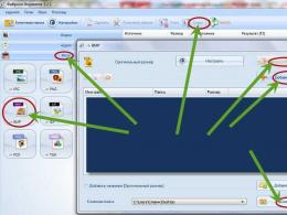
Most electronic components are labeled as listed. standard methods. But there are exceptions. (Fig. 1).

Here, the TIP prefix of this power transistor indicates that it is a power transistor in a plastic case from Texas Instruments. However, the manufacturer applied the MOSPEC logo in front, so the prefix became the second marking element.
This is often found in the marking of integrated circuits, where the manufacturer adds his own coding to the standard type marking.

Fig.2. This integrated circuit has the designation "LM" as a prefix, indicating that it is a National Semiconductor product.
As a few examples, the prefixes "CA" and "MC" are used by KCA and Motorola, respectively. Due to the fact that the same element can be released by different manufacturers and labeled in their own way, there are difficulties in identifying the elements.
Of course, the presence of several manufacturers on the market generates competition, which, as a result, reduces the price of radioelements. For us it's good. On the other hand, each manufacturer introduces something of his own into the marking of elements, thereby making it difficult for us to identify them.
When browsing an integrated circuit catalog, it is probably best to ignore prefix and focus on the other two label elements. Moreover, component suppliers often do not guarantee the supply of devices from specific manufacturers. If you order (say) MC1458CP. but they sent you CA1458E. or vice versa, there is no reason to worry. Both ICs are 1458 dual op amps and there is no practical difference between them. The MC1458CP is made by Motorola or Texas Instruments, and the CA1458E is made by RCA.
Variety of options
Most transistors do not have a suffix in marking. Where it is present, the suffix is usually a single letter and indicates the gain or some other parameter. Typically, the letter "A" is marked with transistors with low gain, the letter "B" with medium gain and the letter "C" with high gain. Specific values or ranges are indicated in the datasheet for the element.
Therefore, if a transistor with the suffix "B" is indicated on the diagram, it is safe to replace it with a transistor with the suffix "C". When replacing with an element with the “A” suffix, its amplification may not be enough and the device will refuse to work or will often go into overload.
There are situations (fortunately, quite rare) when the suffix indicates the location of the pins of the element. For transistors, this designation is "L" or "K". Most transistors have one typical pin configuration. But if your device is not working unknown reasons, check if you have come across transistors with such suffixes.
With integrated circuits, the situation is the opposite. Here, manufacturers often use a suffix to indicate the type of case. And if you ignore the suffix when ordering or specify the wrong one, you run the risk of receiving a chip in a design that will not be compatible with your PCB option.
The situation is complicated by the fact that there are no standards for suffixes and each manufacturer uses its own types of marking. So be extremely careful when ordering chips!
Frequency marking
Some integrated circuits have a suffix that indicates the device's clock speed. This system is used in conjunction with memory and some other computer chips such as microcontrollers and microprocessors. In most cases, additional numbers are actually an extension of the main part of the marking, and not a suffix, since the suffix will be present in the marking and, as mentioned above, will most likely indicate the type of case.
Some PIC microcontrollers, for example, have something like "-20" added to the base number type in the designation. Additional markings indicate the maximum clock frequency (in megahertz) for the chip. You can quite safely use an element with a higher clock frequency than the one listed in the components list. However, faster versions tend to much more expensive than slow ones.
And technology...
But, alas, not everything is so simple. Especially with integrated circuits. The 74th series (TTL) of logic integrated circuits was the main, progenitor of other series and was originally marked according to the rules set out: prefix-main part-suffix. When marking subsequent, improved series, manufacturers began to deviate from the standard marking - between the prefix "74" and the base number, they began to add a marking indicating the family of microcircuits:

This marking may indicate the manufacturing technology and, as a result, the speed (frequency), supply voltages and other parameters.
So the original device 7420 today it may be labeled as 74HC20, 74MCT20 and 74LS20. These are all different families of microcircuits that incompatible between themselves. Therefore, it is important to choose the right type when ordering!
And current!
A similar situation exists in the popularly beloved integral stabilizers L78XX and L79XX. Here, two digits are added to the basic designation, indicating output voltage stabilizers: L7805 - output voltage 5V, L7912 - output voltage -12V.

But in the middle of the number there may be letters that indicate the maximum output current of the stabilizer. There are three marking options, as shown in the table:
So the stabilizer marked "78L15" will output a voltage of 15V and a maximum current of 100mA.
Be careful when reading manufacturers' catalogs and be careful when ordering electronic components!
The article was prepared based on the materials of the journal "Practical Electronics Every Day"
Free translation: Chief editor « »
In the manufacture of electronic devices, novice radio amateurs may have difficulty deciphering the symbols on the diagram of various elements. For this, a small collection of the most common symbols for radio components was compiled. It should be noted that only a foreign version of the designation is given here and there may be differences on domestic schemes. But since most of the schemes and parts are of imported origin, this is fully justified.


The resistor in the diagram is indicated by the Latin letter "R", the number is the conditional serial number according to the diagram. In the rectangle of the resistor, the rated power of the resistor can be indicated - the power that it can dissipate for a long time without destruction. When current passes through the resistor, a certain power is dissipated, which leads to heating of the latter. Most foreign and modern domestic resistors are marked with colored stripes. Below is a table of color codes.


The most common designation system for semiconductor radio components is European. The main designation according to this system consists of five characters. Two letters and three numbers - for wide application. Three letters and two numbers - for special equipment. The letter following them indicates different parameters for devices of the same type.
The first letter is the material code:
A - germanium;
B - silicon;
C - gallium arsenide;
R is cadmium sulfide.
The second letter is the purpose:
A - low-power diode;
B - varicap;
C - low-power low-frequency transistor;
D - powerful low-frequency transistor;
E - tunnel diode;
F - low-power high-frequency transistor;
G - several devices in one case;
H - magnetodiode;
L - powerful high-frequency transistor;
M - Hall sensor;
P - photodiode, phototransistor;
Q - LED;
R - low-power regulating or switching device;
S - low-power switching transistor;
T - powerful regulating or switching device;
U - powerful switching transistor;
X - multiplying diode;
Y - powerful rectifier diode;
Z - zener diode.
click on the picture to enlarge
At practical work associated primarily with the repair of electronic equipment, the task arises to determine the type of electronic component, its parameters, the location of the pins, to decide on a direct replacement or the use of an analogue. Most existing reference books provide information on individual types of radio components (transistors, diodes, etc.). However, it is not enough, and this reference manual serves as a necessary addition to such books. The book presented to the reader on the marking of electronic components contains, in contrast to previously published similar publications, a larger amount of information. It provides data on the letter, color and code marking of components, on the code marking of foreign semiconductor devices for surface mounting (SMD), provides data on the marking of some previously uncovered types of foreign components, gives recommendations on the use and health check of electronic components.
Foreword
1. Resistors
1.1. General information
1.2. Designation and marking of resistors
Notation
Marking of resistors of domestic production
Marking of resistors of foreign production
Resistor assembly marking
1.3. Technical data and markings for frameless SMD resistors
General information
Marking SMD resistors
1.4. Features of the application and marking of variable resistors
BOURNS Variable and Trimmer Resistors
1.5. Resistors with special properties
Thermistors
Varistors
2. Capacitors
2.1. General information
2.2. Designation and marking of capacitors
Domestic designation system
Capacitor marking
Code digital marking
Color coding
2.3. Features of marking some SMD types capacitors
Ceramic 5ME Capacitors
Oxide SMD Capacitors
Tantalum SMD Capacitors
TREC Electrolytic Capacitor Marking
HITANO Capacitors
Tips for practical application
2.4. Trimmer capacitors of foreign companies
2.5. Other types of capacitors
3. Inductors
3.1. General information
3.2. Marking of inductors
Marking inductors for surface mounting
3.3. Choke series D, DM, DP, DPM
4. Marking of quartz resonators and piezo filters
4.1. Marking of resonators and filters of domestic production
4.2. Features of marking resonators and filters of foreign production...
4.3. Features of marking filters manufactured by Murata
5. Marking of semiconductor devices
5.1. Domestic and foreign marking systems
semiconductor devices
Marking R-MOS transistors Harris (Intersil)
Marking of IGBT transistors Harris (Intersil)
Marking of transistors from International Rectifier
Marking of semiconductor devices of the company Mologo1a
5.2. General Diodes
Package Types and Diode Pinouts
Color marking of domestic diodes
Color marking of foreign diodes
Color marking of domestic zener diodes and stabistors
Color marking of domestic varicaps
Alphanumeric code SMD marking foreign diodes
production
Color marking of SMD diodes in SOD-80, DO-213AA, DO-213AB cases
Photodiodes
transistors
Features of code and color marking of domestic transistors
6. Marking of semiconductor SMD radio components
6.1. Identification of SMD components by marking
6.2. Enclosure types SMD transistors
6.3. How to use the system
Equivalents and additional information
7. Features of testing electronic components
7.1. Capacitor testing
7.2. Semiconductor Diode Testing
7.3. Transistor testing
7.4. Testing unijunction and programmable unijunction
transistors
7.5. Testing dinistors, thyristors, triacs
7.6. Determination of the structure and location of the outputs of transistors,
whose type is unknown
7.7. MOSFET Testing
7.8. LED Testing
7.9. Optocouplers testing
7.10. Thermistor testing
7.11. Zener testing
7.12. Arrangement of transistor pins
Appendix 1. Brief reference data on foreign diodes
Appendix 2. Brief reference data on foreign transistors
Appendix 3. Types of housings of microwave transistors
How to decipher the resistance value of a resistor or capacitor capacitance, indicated by colored stripes or dots, is described in this note.
Introduction. Color marking for simple radio components has been used for a very long time. It seems to be easier to apply color stripes to cases than to print numbers on them, especially when the cases are round. In addition, during installation, there is no need to specially ensure that the marking does not turn out to be “face” to printed circuit board- no matter how you put the part, you can always read its face value. To be honest, for many years of doing radio electronics, I have not seen color marking anywhere except for fixed resistors in round cases with wire leads, probably the above is most relevant for them (the case is round, you can turn it over in different ways during installation, and even apply it on a round the body of the figure is more complicated than the stripes). But the theory says that everything will be exactly the same for capacitors.
Step one. Take the resistor in your right hand and take a close look at it (see photo). Four (maybe five) colored stripes around the body are the very color markings that we need to learn how to read, that is, translate into resistance. Resistance is expressed as a number, so the first step is to learn how to translate colors into numbers. For this we use the following table.
* - only for the multiplier (see below)
The first two (or three, if only five) bars indicate the resistance value, the third (fourth) - the multiplier (how many zeros need to be assigned to the value on the right), the last - the tolerance (the maximum deviation of the value of the real resistor from the nominal, in percent).
Step two. The question immediately arises: after all, the resistor has two identical ends, so the number can be written in two ways? For definiteness, the manufacturers came up with several options to mark which end will be the beginning :).
1.
The first strip is moved closer to the edge of the case (towards the terminal) than the last.
2.
The last strip is thicker than the rest.
But I like the third way better, it doesn't always work, but most often you can use it:
3.
Please note that the value cannot start with three colors: silver, gold and black (zero at the beginning of the number is not written). So, if one conclusion has a silver or gold strip, then you should start on the other side. This doesn't always work, but it often does, since the vast majority of fixtures you'll be working with have 5 or 10 percent tolerances.
Step three. We write out the resistance value, then add as many zeros on the right as the multiplier (for example, if the multiplier is orange, that is, "3", then three zeros). If the multiplier is negative, then we do not add zeros, but leave the corresponding number of characters to the right after the comma (one or two). Or, if it's easier for you to understand, multiply the value by the number 10 to the power of the multiplier. One way or another, we got a certain number - this is the resistance of the resistor in ohms.
The last bar, as already mentioned, indicates the maximum possible deviation of the resistance value, in percent, from the resulting number. Usually the schemes are designed for 5-10%, if something particularly accurate is required, the author will most likely tell you about this. As a last resort, there is always an ohmmeter :)
Beginning radio amateurs often face such a problem as the designation of radio components on diagrams and the correct reading of their markings. The main difficulty lies in in large numbers names of elements, which are represented by transistors, resistors, capacitors, diodes and other details. How correctly the diagram is read depends largely on its practical implementation and the normal operation of the finished product.
Resistors
Resistors include radio components that have a strictly defined resistance to flowing through them. electric current. This function designed to reduce the current in the circuit. For example, to make the lamp shine less brightly, power is supplied to it through a resistor. The higher the resistance of the resistor, the less the lamp will glow. For fixed resistors, the resistance remains unchanged, and variable resistors can change their resistance from zero to the maximum possible value.
Each fixed resistor has two main parameters - power and resistance. The power value is indicated on the diagram not with alphabetic or numeric characters, but with the help of special lines. The power itself is determined by the formula: P \u003d U x I, that is, it is equal to the product of voltage and current. This setting has importance, since a particular resistor can only withstand a certain power value. If this value is exceeded, the element will simply burn out, since heat is generated during the passage of current through the resistance. Therefore, in the figure, each line marked on the resistor corresponds to a certain power.

There are other ways to designate resistors in diagrams:

- On circuit diagrams, a serial number is indicated in accordance with the location (R1) and a resistance value of 12K. The letter "K" is a multiple prefix and stands for 1000. That is, 12K corresponds to 12000 ohms or 12 kilo-ohms. If the letter "M" is present in the marking, this indicates 12,000,000 ohms or 12 megaohms.
- In marking with letters and numbers, the letter symbols E, K and M correspond to certain multiple prefixes. So the letter E \u003d 1, K \u003d 1000, M \u003d 1000000. The decoding of the symbols will look like this: 15E - 15 ohms; K15 - 0.15 Ohm - 150 Ohm; 1K5 - 1.5 kOhm; 15K - 15 kOhm; M15 - 0.15M - 150 kOhm; 1M2 - 1.5 mOhm; 15M - 15mOhm.
- In this case, only numerical designations are used. Each includes three digits. The first two of them correspond to the value, and the third to the multiplier. Thus, the factors are: 0, 1, 2, 3 and 4. They mean the number of zeros added to the main value. For example, 150 - 15 ohms; 151 - 150 Ohm; 152 - 1500 Ohm; 153 - 15000 Ohm; 154 - 120000 Ohm.
Fixed resistors
The name of fixed resistors is associated with their nominal resistance, which remains unchanged throughout the entire period of operation. They differ from each other depending on the design and materials.

Wire elements consist of metal wires. In some cases, high resistivity alloys may be used. The basis for winding the wire is a ceramic frame. These resistors have high precision nominal, and a serious disadvantage is the presence of a large self-inductance. In the manufacture of film metal resistors, a metal with a high resistivity is sprayed onto the ceramic base. Due to their qualities, such elements are most widely used.
The design of carbon fixed resistors can be film or bulk. In this case, the qualities of graphite are used as a material with high resistivity. There are other resistors, for example, integral ones. They are used in specific integrated circuits where the use of other elements is not possible.
Variable resistors
Beginning radio amateurs often confuse a variable resistor with a variable capacitor, because outwardly they are very similar to each other. However, they have completely different functions, and there are also significant differences in the display on circuit diagrams.

The design of the variable resistor includes a slider that rotates along the resistive surface. Its main function is to adjust the parameters, which consists in changing internal resistance before desired value. This principle is based on the operation of the sound control in audio equipment and other similar devices. All adjustments are made by smooth change voltage and current in electronic devices.
The main parameter of a variable resistor is resistance, which can vary within certain limits. In addition, it has an installed power that it must withstand. All types of resistors have these qualities.

On domestic circuit diagrams, elements variable type are indicated in the form of a rectangle, on which two main and one additional output are marked, located vertically or diagonally passing through the icon.
On foreign schemes, the rectangle is replaced by a curved line with the designation of an additional output. Next to the designation, the English letter R is placed with the serial number of one or another element. The value of the nominal resistance is put next to it.
Connection of resistors
In electronics and electrical engineering, resistor connections in various combinations and configurations are quite often used. For greater clarity, a separate section of the circuit with serial, parallel and should be considered.

With a series connection, the end of one resistor is connected to the beginning of the next element. Thus, all resistors are connected one after another, and a total current of the same value flows through them. There is only one path for current to flow between the start and end points. With an increase in the number of resistors connected in a common circuit, there is a corresponding increase in the total resistance.

Such a connection is considered parallel when the initial ends of all resistors are combined at one point, and the final outputs at another point. Current flows through each individual resistor. As a result parallel connection as the number of connected resistors increases, so does the number of paths for current to flow. The total resistance in such a section decreases in proportion to the number of connected resistors. It will always be less than the resistance of any resistor connected in parallel.

Most often in radio electronics, a mixed connection is used, which is a combination of parallel and series options.
In the presented circuit, resistors R2 and R3 are connected in parallel. The series connection includes resistor R1, a combination of R2 and R3, and resistor R4. In order to calculate the resistance of such a connection, the entire circuit is divided into several simple sections. After that, the resistance values are summed up and the overall result is obtained.
Semiconductors
A standard semiconductor diode consists of two terminals and one rectifying electrical junction. All elements of the system are combined in a common body made of ceramic, glass, metal or plastic. One part of the crystal is called the emitter, due to the high concentration of impurities, and the other part, with a low concentration, is called the base. The marking of semiconductors on the diagrams reflects them design features and specifications.

For the manufacture of semiconductors, germanium or silicon is used. In the first case, it is possible to achieve a higher transmission coefficient. Germanium elements are characterized by increased conductivity, for which even a low voltage is sufficient.
Depending on the design, semiconductors can be point or planar, and according to technological features, they can be rectifier, pulsed or universal.
Capacitors
The capacitor is a system that includes two or more electrodes made in the form of plates - linings. They are separated by a dielectric, which is much thinner than the capacitor plates. The whole device has mutual capacitance and has the ability to save electric charge. On the the simplest scheme the capacitor is presented in the form of two parallel metal plates separated by some kind of dielectric material.

On the circuit diagram next to the image of the capacitor is indicated its nominal capacitance in microfarads (uF) or picofarads (pF). When designating electrolytic and high-voltage capacitors, after the nominal capacitance, the value of the maximum operating voltage, measured in volts (V) or kilovolts (kV), is indicated.
variable capacitors
Capacitors with variable capacitance are denoted by two parallel segments, which are crossed by an inclined arrow. Movable plates connected at a certain point in the circuit are shown as a short arc. Near it, the designation of the minimum and maximum capacity is affixed. A block of capacitors, consisting of several sections, is combined using a dashed line crossing the adjustment signs (arrows).

The designation of the trimmer capacitor includes an oblique line with a dash at the end instead of an arrow. The rotor is displayed as a short arc. Other elements - thermal capacitors are designated by the letters SK. In its graphical representation, a temperature symbol is affixed near the non-linear adjustment sign.
Permanent Capacitors
Graphic designations of capacitors with a constant capacitance are widely used. They are depicted as two parallel segments and conclusions from the middle of each of them. The letter C is placed next to the icon, after it is the serial number of the element and, with a small interval, the numerical designation of the nominal capacity.


When using a capacitor with in a circuit, an asterisk is applied instead of its serial number. The rated voltage value is indicated only for high voltage circuits. This applies to all capacitors, except for electrolytic ones. The digital symbol for voltage is placed after the designation of the capacitance.
The connection of many electrolytic capacitors requires polarity. In the diagrams, a “+” sign or a narrow rectangle is used to indicate a positive lining. In the absence of polarity, both plates are marked with narrow rectangles.
Diodes and zener diodes
Diodes are among the simplest semiconductor devices that operate on the basis of an electron-hole junction, known as a p-n junction. The property of one-way conductivity is clearly conveyed in graphic symbols. A standard diode is depicted as a triangle symbolizing the anode. The vertex of the triangle indicates the direction of conduction and abuts against the transverse line denoting the cathode. The entire image is crossed in the center by an electric circuit line.

For the letter designation VD is used. It displays not only individual elements, but also entire groups, for example, . The type of a particular diode is indicated next to its reference designation.
The base symbol is also used to designate zener diodes, which are semiconductor diodes with special properties. There is a short stroke in the cathode directed towards the triangle symbolizing the anode. This stroke is located invariably, regardless of the position of the zener diode icon on the circuit diagram.
transistors
Most electronic components have only two pins. However, elements such as transistors are equipped with three terminals. Their designs come in a variety of types, shapes and sizes. General principles they work the same, and small differences are associated with technical specifications specific element.

Transistors are primarily used as electronic switches to turn various devices on and off. The main convenience of such devices is the ability to switch high voltage using a low voltage source.
At its core, each transistor is a semiconductor device with the help of which electrical oscillations are generated, amplified and converted. The most widespread are bipolar transistors with the same electrical conductivity of the emitter and collector.
In the diagrams, they are indicated by the letter code VT. The graphic image is a short dash, from the middle of which a line departs. This symbol represents the base. Two inclined lines are drawn to its edges at an angle of 60 0, representing the emitter and collector.

The electrical conductivity of the base depends on the direction of the emitter needle. If it is directed towards the base, then the electrical conductivity of the emitter is p, and that of the base is n. When the arrow is directed in the opposite direction, the emitter and base change the electrical conductivity to the opposite value. Knowledge of electrical conductivity is necessary for correct connection transistor to the power supply.
In order to make the designation on the diagrams of the radio components of the transistor more visual, it is placed in a circle, meaning the case. In some cases, a metal case is connected to one of the terminals of the element. Such a place on the diagram is displayed as a dot, affixed where the output intersects with the body symbol. If there is a separate output on the case, then the line indicating the output can be connected to a circle without a dot. Near the positional designation of the transistor, its type is indicated, which can significantly increase the information content of the circuit.
Letter designation on diagrams of radio components
|
Basic designation |
Element name |
Additional designation |
Device type |
|
Device |
current regulator |
||
|
Relay box |
|||
|
Device |
|||
|
Converters |
Speaker |
||
|
Thermal sensor |
|||
|
Photocell |
|||
|
Microphone |
|||
|
Pickup |
|||
|
Capacitors |
Power capacitor bank |
||
|
Charging Capacitor Block |
|||
|
Integrated circuits, microassemblies |
IC analog |
||
|
IC digital, logical element |
|||
|
Elements are different |
Thermal electric heater |
||
|
Lighting lamp |
|||
|
Surge arresters, fuses, protective devices |
Discrete instantaneous current protection element |
||
|
The same, for the current of inertial action |
|||
|
fuse |
|||
|
Discharger |
|||
|
Generators, power supplies |
Battery pack |
||
|
Synchronous compensator |
|||
|
Generator exciter |
|||
|
Indicating and signaling devices |
Sound alarm device |
||
|
Indicator |
|||
|
Light signaling device |
|||
|
Signal board |
|||
|
Signal lamp with green lens |
|||
|
Signal lamp with red lens |
|||
|
Signal lamp with white lens |
|||
|
Ionic and semiconductor indicators |
|||
|
Relays, contactors, starters |
Current relay |
||
|
Relay index |
|||
|
Relay electrothermal |
|||
|
Contactor, magnetic starter |
|||
|
Time relay |
|||
|
Voltage relay |
|||
|
Close command relay |
|||
|
Trip command relay |
|||
|
Intermediate relay |
|||
|
Inductors, chokes |
Throttle fluorescent lighting |
||
|
Action time meter, hours |
|||
|
Voltmeter |
|||
|
Wattmeter |
|||
|
Power switches and disconnectors |
Automatic switch |
||
|
Resistors |
Thermistor |
||
|
Potentiometer |
|||
|
Measuring shunt |
|||
|
Varistor |
|||
|
Switching device in control, signaling and measuring circuits |
Breaker or switch |
||
|
push button switch |
|||
|
Automatic switch |
|||
|
Autotransformers |
Current transformer |
||
|
Voltage transformers |
|||
|
Converters |
Modulator |
||
|
Demodulator |
|||
|
Power Supply |
|||
|
Frequency converter |
|||
|
Electrovacuum and semiconductor devices |
diode, zener diode |
||
|
Electrovacuum device |
|||
|
Transistor |
|||
|
Thyristor |
|||
|
Contact connectors |
current collector |
||
|
High frequency connector |
|||
|
Mechanical devices with electromagnetic drive |
Electromagnet |
||
|
electromagnetic lock |