Analysis and calculation of electrical circuits. Calculation of linear DC electrical circuits
Methodological instructions for the sections of the course
DC electrical circuits. Electrical circuit- a set of devices designed to receive, transmit and convert into other types of electrical energy. It consists of a source and receiver of electrical energy connected by connecting wires. In addition to these elements, the circuit includes switching and protective equipment and electrical measuring instruments. These devices serve to control and monitor the operation of the circuit, as well as to protect its elements from overloads.
The main task of the analysis of electrical circuits is to determine the currents of all branches for a given circuit configuration and known parameters of all its elements. When calculating currents, they often depict not a real circuit, but its equivalent circuit. equivalent circuit- this is a graphical representation of a real circuit using ideal elements, the parameters of which are the parameters of the real elements included in the circuit. Measuring instruments, protection equipment and on-off equipment are not indicated on the equivalent circuit.
In the equivalent circuit, branches, nodes and contours are distinguished. Branch is a section of a circuit in which the same current flows in any section. Knot is the point where at least three branches converge. Circuit- any closed path for electric current.
A contour is called independent if it has at least one element belonging only to it.
Circuit elements can be connected in series and in parallel. When connected in series, the same current flows in all elements. When connected in parallel, the circuit elements are connected to one pair of nodes.
To calculate the currents in the branches of the circuit, apply Kirchhoff and Ohm's laws.
Kirchhoff's first law refers to a node and reads:
the algebraic sum of the currents converging in the node is equal to zero.
where i is the current number;
n is the number of currents converging in the node.
Kirchhoff's second law refers to the contour, it reads:
the algebraic sum of the EMF acting in the circuit is equal to the algebraic sum of the voltage drops in the same circuit.
where i is the number of the circuit branch;
n is the number of branches included in the circuit.
Kirchhoff's laws are used to calculate complex branched circuits that include several energy sources. In this case, it is necessary to compose p \u003d m + (n-1) equations, where m is the number of independent circuits, n is the number of nodes.
Select the direction of bypassing the contours (there will be fewer errors in the future if the direction is the same in all contours).
Arbitrarily indicate the direction of currents in the branches of the circuit.
Compose the necessary equations according to the first law of Kirchhoff.
Compose the necessary equations according to the second Kirchhoff law, considering positive currents and EMF, coinciding with the direction of bypassing the circuit.
Solve the resulting system of equations by any known method.
Check the correctness of the solution by drawing up a power balance.
Solution example 1.
For the electrical circuit shown in fig. 1.1., according to the values \u200b\u200bof the EMF of the sources and the resistances of the resistors, find the values \u200b\u200bof the currents in all branches and their directions.
E 1 \u003d 45 V; E 2 \u003d 60 V; R 01 \u003d 0.1 Ohm; R 02 \u003d 0.15 Ohm; R 1 \u003d R 2 \u003d R 5 \u003d 2 ohms; R 3 \u003d 10 Ohm; R 4 \u003d 4 ohms.
Since the resistors R 1 , R 5 and R 4 are connected in series, then I 4 =I 5 =I 1 ; similarly I 3 \u003d I 02 \u003d I 2.
Based on the first law of Kirchhoff for node “a” we have I 1 +I 01 -I 2 =0.
Based on the second Kirchhoff law for the circuit R 1 -R 5 -R 4 -E 1 - R 01 -R 1 we get I 1 (R 1 +R 5 +R 4) -I 01 R 01 \u003d -E 1.
Similarly, for the circuit R 2 -R 01 -E 1 - R 3 - E 2 -R 02 -R 2:
I 2 (R 3 + R 02 + R 2) + I 01 R 01 \u003d E 1 - E 2.
Substituting the values of EMF and resistance gives a system of equations:
I 1 +I 01 -I 2 \u003d 0
8I 1 -0.1I 01 + 0I 2 \u003d -45
0I 1 +0.1I 01 +12.15I 3 = -15
Solving the system of equations gives:
I 1 \u003d -5.57 A, I 01 \u003d 4.30 A, I 2 \u003d -1.27 A.
Negative values of the currents I 1 and I 2 mean that initially their directions were chosen incorrectly and their directions in the diagram must be changed to the opposite ones.
To check the correctness of the solution, it is necessary to draw up a power balance
The product E i I i is taken with the “+” sign if the directions of the EMF and current in the “i” branch are the same. E 1 I 01 + E 2 I 2 \u003d I 1 2 (R 1 + R 5 + R 4) + I 2 2 (R 3 + R 02 + R 2) + I 01 2 R 01. Substitution of EMF values, currents and resistances and calculation give: 269.7=269.7, i.e. the problem is solved correctly.
When calculating complex circuits with a large number of energy sources, it is more rational to use loop current method, which makes it possible to almost halve the number of equations.
In the method of loop currents, independent variables are loop currents conditionally closed by elements of independent loops.
To find the loop currents of each independent loop, it is necessary to compose the equations of the second Kirchhoff law and solve the resulting system of linear equations. When calculating, it is recommended to adhere to the following sequence:
Select all independent contours.
Specify the directions for bypassing the contours (it is better if the directions for bypassing all contours are the same).
Indicate the directions of the loop currents in each circuit (to avoid errors when compiling equations, it is recommended to choose the directions of the loop currents to coincide with the directions of the bypass).
For all independent circuits, compose the equations of the second Kirchhoff law.
Solve the resulting system of equations.
Check the correctness of her solution.
Based on the calculated values of the loop currents, determine the magnitude of the currents in the branches and their directions.
Draw up a power balance.
Consider the solution using the example of the previous problem (Fig. 1.2.).
According to the features given in the definition of an independent contour, the following independent contours can be distinguished: R 1 -R 5 -R 4 -E 1 -R 01 -R 1 and R 2 -R 01 -E 1 -R 3 -E 2 -R 02 -R 2 . In accordance with the chosen directions of bypass and loop currents, we write the equations of the second Kirchhoff law
I k1 (R 01 + R 1 + R 5 + R 4) -I k2 R 01 \u003d -E 1
I k1 R 01 + I k2 (R 01 + R 3 + R 02 + R 2) \u003d E 1 -E 2.
Substituting the values of resistance and EMF and solving the resulting system of equations gives: I k1 \u003d -5.57 A, I k2 \u003d -1.27 A.
Since only the loop current I k1 flows in the outer branch R 1 -R 5 -R 4, then I 1 \u003d I 4 \u003d I 5 \u003d 5.57 A, and their direction is opposite to the direction I k1. Similarly, I 2 \u003d I 3 \u003d 1.27 A.
In the branch R 01 -E 1, two loop currents flow in opposite directions, therefore, to find the current I 01, it is necessary to subtract the smaller one from the larger loop current and take the direction of the larger one, i.e.
I 01 \u003d I k2 -I k1 \u003d -1.27- (-5.57) \u003d 4.3 A.
The power balance is compiled as in the previous problem.
Circuits with a single energy source can be calculated using only Ohm's law by equivalent transformation of the chain.
Solution example 2.
Consider the calculation on the example of the circuit shown in fig. 1.3.
For the circuit shown in fig. 1.3, find the currents in all branches, determine the EMF of the source E and instrument readings if: R 0 \u003d 0.15 Ohm; R 1 \u003d 0.7 Ohm; R 2 \u003d 40 Ohm; R 3 \u003d 8 ohms; R 4 \u003d 4 ohms; R 5 \u003d 2.4 ohms; R 6 \u003d 4 ohms; I 2 \u003d 0.25 A.
1. In accordance with the positive direction of the EMF-E, we indicate the directions of the currents in all branches.
2. According to Ohm's law for the circuit section, we find the voltage across the resistor R 2
U 2 \u003d I 2 R 2 \u003d 0.25 * 40 \u003d 10 V.
3. Since R 3 and R 2 are connected to the same pair of nodes a-b, the voltage across the resistor R 3 is equal to U 2, and then I 3 can be found according to Ohm's law for the circuit section.
4. Based on the first Kirchhoff law for node “b”, we have:
I A \u003d I 2 + I 3 \u003d 0.25 + 1.25 \u003d 1.5 A.
5. If the resistance of the ammeter is neglected, then the voltage in the section R 4 -R 5 will be equal to U 2 and then
6. Based on the first Kirchhoff law, for node “a” we can write:
I 6 \u003d I 2 + I 3 + I 4 \u003d 0.25 + 1.25 + 1.56 \u003d 3.06 A.
7. In the section R 1 -R 0 -E-R 6, all elements are connected in series and then
I 6 \u003d I 1 \u003d 3.06 A.
U 6 \u003d I 6 R 6 \u003d 3.06 * 4 \u003d 12.24 B.
9. Based on the second law of Kirchhoff, the reading of the voltmeter Uv \u003d U 6 + U 2 \u003d 12.24 + 10 \u003d 22.24 V.
10. Based on the second law of Kirchhoff, the EMF of the source
E \u003d I 1 R 0 + I 1 R 1 + U ad \u003d 3.06 * 0.15 + 3.06 * 0.7 + 22.24 \u003d 24.84.
The verification of the correctness of the solution is carried out by the power balance as indicated earlier.
AC circuits. Current, the magnitude and direction of which change with time, is called variable. Of all the variety of alternating currents, the current that changes according to a sinusoidal law is most widely used. Sinusoidal currents occur in circuits under the action of sinusoidal EMF and voltages.
The value of the sinusoidal current at a given time is called instantaneous (denoted by i).
The maximum value of the sinusoidal current is called the amplitude (denoted by I m).
The effective value of a sinusoidal current is such a direct current that, during one period, releases the same amount of heat as a given alternating current (denoted by I). Voltmeters and ammeters are graduated in effective values. The effective and amplitude values are related by the following relationship:
When analyzing the electrical state of circuits, the calculation of currents is carried out either for effective or for amplitude values. The most common method for calculating sinusoidal current circuits is symbolic. In this case, the sinusoidal value is represented by a rotating vector whose position on the complex plane at a given time is described by a complex number (symbol).
There are three forms of writing a complex number: algebraic, exponential, and trigonometric.
In algebraic form, a complex number is written as a polynomial, for example
where a is the projection of the vector onto the axis of real values;
b - projection of the vector onto the axis of imaginary quantities;
j is the imaginary unit.
The algebraic notation is convenient for adding and subtracting complex numbers.
In exponential form, a complex number is written as
A=Aejj ,
where is the modulus of a complex number.
j=arctg b/a - the angle formed by the vector with the positive direction of the axis of the effective values.
The exponential notation is convenient for multiplying and dividing complex numbers.
In trigonometric form, a complex number is written as a polynomial
A=ACosj+jASinj.
The trigonometric form of notation makes it easy to switch from exponential to algebraic notation. In a symbolic calculation, all equations for direct current circuits remain valid for alternating current circuits, with the only difference being that all the quantities included in them are taken in complex form.
Solution example 3.
For the circuit shown in Fig. 1.4., according to the voltage and resistance values, determine the instrument readings, as well as the total and reactive power, build a vector diagram.
The initial phase of the voltage is taken equal to zero, then the complex of the applied voltage will be equal to
U\u003d 127 e jo V.
Impedance complex of series-connected elements R, L and C
Z=R+j(X L -X c).
Hence the impedance complexes of the branches
Z 1 =jX L1 =j5=5e j90 ohm
Z 2 \u003d R 2 -jX c2 \u003d 3-j4 \u003d 5e -j53 Ohm.
According to Ohm's law, the complexes of currents in the branches are determined
The real part of the complex power is the active power P, and the imaginary part is the reactive power Q.
The construction of a vector diagram begins with the choice of a scale for current and voltage.
On the selected scales, the voltage and current vectors are plotted in accordance with the calculated values. Angles are measured from the +1 axis. Positive angles are laid in the opposite direction of the clockwise movement. The current vector in the unbranched part of the circuit is found by adding the current vectors I 1 and I 2 .
Solution example 4.
In the circuit shown in Fig. 1.6., there is a voltage u=U m Sinwt, with a frequency of 50 Hz. Find instrument readings, reactive and apparent power, build a vector diagram if U m \u003d 282 V, R \u003d 3 Ohm, L \u003d 19.1 mH, C \u003d 1592.4 uF.
1. Since the voltmeter is calibrated in effective values, the voltage at the circuit terminals will be equal to:
2. Inductance reactance L
Complex inductive resistance
jX L \u003d j6 \u003d 6e j90 Ohm.
3. Capacitor reactance C
Complex capacitance
JX c \u003d -j2 \u003d 2e -j90 Ohm.
4. Complex circuit impedance
Z=R+j(X L -X c)=3+j(6-2)=3+j4=5e j arctg4/3 =5e j53 Ohm.
5. The initial phase of the voltage applied to the circuit terminals is taken equal to zero, then the voltage complex at the circuit terminals
U=200e jo B.
6. The current complex is found according to Ohm's law
I=U/Z=200e j0 /(5e j53)=40e -j53 A.
Ammeter reading I A =40 A.
7. Stress complex in section R
Voltmeter reading in section R
8. Stress complex in section L
U L= I jX L \u003d 40e -j53 6e j90 \u003d 240e j37 B.
Voltmeter reading in section L
9. Voltage complex in section C
U C =80 V.
10. Integrated total power circuit:
Total power S=8000 VA.
The real part of the complex apparent power is the wattmeter reading
The imaginary part of the complex total power is the reactive power
11. Phase difference between voltage and current:
j=j U - j I =0-(-53)=53 0 .
12. Phase meter reading
Cosj=Cos53=0.602.
When constructing a vector diagram in the selected scales of current and voltage, current and voltage vectors are built, the complexes of which are calculated. Positive angles are counted from the axis of real values in the direction opposite to the clockwise movement.
The voltage vector applied to the circuit terminals is found by adding U R, U L and U c according to the rules of vector addition.
Three-phase electrical circuits . A set of electrical circuits in which three sinusoidal electromotive forces of the same frequency and amplitude are created by one energy source, the vectors of which are shifted relative to each other by an angle of 120 0, is called three-phase system or three-phase circuit. Each of the circuits included in the three-phase system is called phase; phase designations - A, B, C. The currents flowing in the phases of the receiver are called phase.
Three-phase receivers can be included star or triangle; they can be symmetrical or asymmetrical. The receiver is called symmetrical, if the impedance complexes of its phases are equal, i.e. Z a = Z b= Z c.
Star- this is such a connection in which the ends of the phases, denoted by the letters x, y, z, are connected into one node, which is called neutral point, and the beginnings of the phases, denoted by the letters a, b, c, are connected to the source. The neutral point of the receiver is connected to the neutral point of the source.
The wires connecting the beginning of the receiver and source phases are called linear; they run line currents. The wire connecting the neutral points is called neutral, or null.
Triangle- this is a connection in which the end of the previous phase is connected to the beginning of the next.
One of the advantages of three-phase systems is the presence of two operating voltages - phase and linear.
Phase voltage called the voltage between the beginning and end of the same phase.
line voltage is the voltage between the beginnings of two phases.
For receivers connected according to the “star” scheme with a neutral wire, the following relations are fulfilled:
I l \u003d I f U l \u003d.
The current in the neutral wire can also be found from the vector diagram.
For receivers connected according to the “triangle” scheme, the following relations are fulfilled:
U l \u003d U f I l \u003d.
However, if the receiver asymmetrical, linear currents do not obey the indicated relation and can be found either analytically, as the difference between the complexes of phase currents
or from a vector diagram.
Here, , - complexes of currents in linear wires;
Complexes of phase currents in receiver phases.
When calculating the complexes of currents in the phases of the receiver, they are determined separately for each phase based on Ohm's law.
I a = U a / Z a; I b= U b/ Z b; I c= U c/ Z c.
Here , , - complexes of phase voltages,
Z a , Z b, Z c - complexes of phase impedances.
Solution example 5.
For an active-inductive receiver connected according to the “star” circuit with a neutral wire (Fig. 1.8.) In a network with linear voltage U l \u003d 380 V, find the phase and linear currents, as well as the current in the neutral wire, the active powers of the individual phases and the active power of the receiver, if R a \u003d 3 Ohms, R b \u003d 4 Ohms, R c \u003d 6 Ohms, X a \u003d 4 Ohms, X b \u003d 3 Ohms, X c \u003d 8 Ohms.
1. Find the effective value of the phase voltage
2. The initial voltage phase in phase “a” is taken equal to zero, then the phase voltage complexes will be:
.
4. Calculate complexes of phase currents
I a = U a / Z a =220e j0 /(5e j53)=44e -j53 A.
I b= U b/ Z b =220e -j120 /(5e j37)=44e -j157 A.
I c= U c/ Z c =220e j120 /(10e j53)=22e j67 A..
5. Since the receiver is connected by a “star”, the linear currents are equal to the phase ones.
6. Find the current in the neutral wire
The effective value of the current in the neutral wire:
7. Determine the complex total power of the phases of the receiver
Active power of phase “a”: P a \u003d 5825 W.
Reactive power of phase “a”: Q a \u003d 7730 Var.
Active power of phase “b”: Р b =7730 W.
Reactive power of phase “b”: Q b =5825 Var.
Active power of phase “c”: Р c =2912 W.
Reactive power of phase “c”: Q c =3865 Var.
8. Calculate the active power of the receiver.
The active power of a three-phase receiver is equal to the sum of the active powers of the individual phases.
P \u003d P a + P b + P c \u003d 5825 + 7730 + 2912 \u003d 16469 W.
For the convenience of constructing a vector diagram, the coordinate axes are rotated by 90 0 in the opposite direction to the clockwise movement.
The phase voltage vectors are plotted on the selected scale. The phase voltage vectors are built in accordance with the calculated values of the phase current complexes. Positive angles are laid in the direction opposite to the clockwise movement, from the axis of real values. The current vector in the neutral wire is found by adding the phase current vectors according to the rules of vector addition.
Homework completion #1 (part one)
Subject « Calculation of a complex DC circuit»
Guidelines
Objective: mastering the methods of analysis of linear electrical circuits of direct current.
- Exercise:
1) Draw a diagram according to the option.
2) Determine the number of branches, nodes and contours.
3) Compose equations according to the first and second laws of Kirchhoff.
4) Determine the currents of all branches by the method of nodal potentials and the method of loop currents.
6) Determine the current in the branch (the branch number in the table corresponds to the resistor number in the circuit) using the equivalent generator method.
7) Determine the readings of the instruments.
8) Build a potential diagram.
9) Draw conclusions.
2. Instructions for the design of settlement and graphic work
1) Draw a diagram in accordance with the number of the option (Scheme Appendix 1, table Appendix 2). The variant number corresponds to the number in the educational journal.
2) Homework is done on A4 sheets on one side of the sheet, it is advisable to use computer programs.
3) Make a drawing of the circuit and its elements in accordance with GOST.
4) A sample of the design of the title page is presented in Appendix 3.
5) Each task item must have a heading. Formulas, calculations, diagrams should be accompanied by the necessary explanations and conclusions. The obtained values of resistances, currents, voltages and powers must end with units of measurement in accordance with the SI system.
6) Graphs (diagrams) must be made on mm paper with obligatory graduation along the axes and indication of scales for current and voltage.
7) If a student made mistakes when doing homework, then the correction is carried out on separate sheets with the heading “Work on mistakes”.
8) Deadline for homework 5th week of the semester.
3. Theoretical Introduction
3.1 Topological components of electrical circuits
Number of branches - R
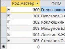
b) knot– q the junction of three or more branches, the nodes are potential or geometric fig. one

Four geometric nodes (abcd) and three potential nodes (abc) since the potentials of nodes c and d are equal: φ c = φ d
in) Circuit- a closed path passing through several branches and nodes of an extensive electrical circuit - abcd, fig. 1. An independent circuit with at least one new branch.
3.2. Power balance
We make equations for determining the power of the receiver:
Σ R pr = Σ I²· R
We compose equations for determining the power of the source:
Σ P ist =Σ E· I
The balance converges under the condition that the source and receiver power equations are equal, i.e.: Σ R pr = Σ P ist
The balance is considered converged if the error of non-convergence is no more than 2%.
3.3. Equivalent transformations of passive sections of an electric circuit
Connections are: series, parallel and mixed, star, delta, bridge.
1. serial connection when the current in each element is the same.
| R eq \u003d R 1 + R 2 + R 3 I=E/R eq U \u003d U 1 + U 2 + U 3 \u003d = R1· I+R2· I+R3· I=R eq · I |
Serial connection properties:
a) Circuit current and voltage depends on the resistance of any of the elements;
b) The voltage on each of the series-connected elements is less than the input;
Ui < U
c) The series connection is a voltage divider.
2. Parallel connection
A connection in which all sections of the circuit are connected to the same pair of nodes that are under the influence of the same voltage.
Parallel connection properties :
1) The equivalent resistance is always less than the smallest of the branch resistances;
2) The current in each branch is always less than the source current. The parallel circuit is a current divider;
3) Each branch is under the same source voltage.
3.mixed connection
It is a combination of serial and parallel connections.
Method of equivalent transformations
Solving any problem with a single power supply using Ohm's laws, Kirchhoff's and circuit folding skills.
|
|
|


3.4 Methods for calculating electrical circuits with multiple power supplies
3.4.1 Method using Kirchhoff's laws.
The most accurate method, but it can be used to determine the parameters of a circuit with a small number of circuits (1-3).
Algorithm :
1. Determine the number of nodes q, branches p and independent circuits;
2. Set the directions of currents and circuit bypasses arbitrarily;
3. Set the number of independent equations according to the 1st Kirchhoff law ( q- 1) and compose them, where q is the number of nodes;
4. Determine the number of equations according to the 2nd Kirchhoff law ( p – q+ 1) and compose them;
5. Solving the equations together, we determine the missing parameters of the circuit;
6. Based on the received data, the calculations are checked by substituting the values into the equations according to the 1st and 2nd Kirchhoff laws or by compiling and calculating the power balance.
Example:
We write these equations according to the rules:
for node "a" I 1 -I 2 -I 4 = 0
for node "b" I 4 -I 5 -I 3 = 0
for circuit 1 R 1 I 1 +R 2 I 2 =E 1 - E 2
for circuit 2 R 4 I 4 +R 5 I 5 -R 2 I 2 =E 2
for circuit 3 R 3 I 3 -R 5 I 5 =E 3
Rule: if the EMF and current have the same direction as the circuit bypass direction, then they are taken from "+", if not, then from "-".
Let's make the power balance equations:
P etc = R 1 I 1²+ R 2 I 2²+ R 3 I 3² + R 4 I 4²+ R 5 I 5²
P ist =E 1 · I 1 + E 3 · I 3 - E 2 · I 2
3.4.2 Loop current method
Using this method, the number of equations is reduced, namely, equations according to the 1st Kirchhoff law are excluded. The concept of loop current is introduced (such currents do not exist in nature - this is a virtual concept), equations are compiled according to the second Kirchhoff law.
Consider our example in Fig. 2

Loop currents are marked Im, In, Il, their directions are given, as shown in Fig. 2
Solution algorithm :
1. Let's write the real currents through the loop: along the external branches I 1 = Im,
I 3 = Il, I 4 = In and on adjacent branches I 2 = Im - In, I 5 = In - Il
2. We compose equations according to the second Kirchhoff law, since there are three contours, therefore there will be three equations:
for the first circuit Im·( R 1 + R 2) - In· R 2 = E 1 - E 2 , "-" sign before In is set because this current is directed against Im
for the second circuit - Im· R 2 + (R 2 + R 4 + R 5) · In - Il· R 5 = E 2
for the third circuit - In· R 5 + (R 3 + R 5) · Il = E 3
3. Solving the resulting system of equations, we find the loop currents
4. Knowing the loop currents, we determine the actual currents of the circuit (see paragraph 1.)
3.4.3 Nodal potential method
The proposed method is the most effective of the proposed methods.
The current in any branch of the circuit can be found using the generalized Ohm's law. To do this, it is necessary to determine the potentials of the circuit nodes.
If the circuit contains n nodes, then the equations will be (n-1):
- Ground any circuit node φ = 0;
- It is necessary to determine (n-1) potentials;
- Equations are compiled according to the first Kirchhoff law according to the type:
φ 1 G 11+φ 2 G 12 +…+φ (n-1)G 1,(n-1) = I 11
φ 1 G 21 + φ 2 G 22 +…+φ (n-1) G 2,(n-1) = I 22
…………………………………………………
…………………………………………………
φ 1 G (n-1),1 +φ 2 G (n-1),2 +…+φ (n-1) G (n-1), (n-1) = I (n-1), (n-1)
where I 11 … I(n -1), (n -1) nodal currents in branches with EMF connected to this node, G kk is the intrinsic conductivity (the sum of the conductivities of the branches at node k), G km– mutual conductivity ( the sum of the conductivities of the branches connecting the nodes k and m) taken with the "-" sign.
- The currents in the circuit are determined by the generalized Ohm's law.
Example:
φ a( + + ) - φ b = E 1 + E 2
φ b (++) - φ a= - E 3
identifying potentials φ a and φ b, find the circuit currents. Drawing up formulas for calculating currents is carried out in accordance with the rules of signs of EMF and voltages, when calculating according to the generalized Ohm's law (see lecture 1).


The correctness of the calculation of currents is checked using Kirchhoff's laws and power balance.
3.4.4 Two knot method
The two knot method is a special case of the nodal potential method. It is used when the circuit contains only two nodes (parallel connection).
Algorithm:
- Positive directions of currents and voltage between two nodes are set arbitrarily;
- Equation for determining the inter-nodal voltage
 ,
,
where G is the conductance of the branch, J– current sources;
- rule: GE and J are taken with a "+" sign if E and J directed to a node with great potential;
- The circuit currents are determined by the generalized Ohm's law
Example:


Drawing up formulas for calculating currents is carried out in accordance with the rules of signs of EMF and voltages, when calculating according to the generalized Ohm's law (see lecture 1).


3.4.5 Active two-terminal method
This method is used when it is necessary to calculate the parameters of one branch in a complex circuit. The method is based on the active two-terminal network theorem: “Any active two-terminal network can be replaced by an equivalent two-terminal network with parameters E equiv and R equiv or J equiv and G equiv, the operating mode of the circuit will not change.”
Algorithm:
1. Open the branch in which you want to define parameters.
2. Determine the voltage at the open terminals of the branch, i.e. at idle Eeq = Uxx favorite method.
3. Replace the active two-terminal network, i.e. circuit without a branch under study, passive (exclude all power sources, leaving their internal resistances, not forgetting that the ideal EMF Rext= 0, and for an ideal current source Rext= ∞). Determine the equivalent resistance of the resulting circuit Req.
4. Find the current in the branch using the formula I = Eeq/(R+Req) for the passive branch and
I = E ± Eeq/(R+Req) for the active branch.
3.5 Building a potential diagram
The distribution of potentials in an electrical circuit can be represented using a potential diagram.
The potential diagram is a dependency φ(R) in the form of a graph, on which the vertical axis shows the potential values of a successive series of points of the selected circuit, and the horizontal axis shows the sum of the resistance values of the successively passed sections of the circuit of this circuit. The construction of a potential diagram starts from an arbitrarily chosen point of the contour, the potential of which is taken as zero φ 1 = 0. Sequentially bypass the selected contour. If the construction of the diagram started at point 1, then it should end at the same point 1. The potential jumps on the graph correspond to the voltage sources included in the circuit.
1.1. Determination of instrument readings
A voltmeter measures the voltage (potential difference) between two points in an electrical circuit. To determine the voltmeter reading, it is necessary to draw up an equation according to the second Kirchhoff law along the circuit, which includes the measured voltage.
The wattmeter shows the power of a section of an electrical circuit, which is determined by the Joule-Lenz law.
4. Example:
Given : R 1 = R 5 \u003d 10 Ohm, R 4 = R 6 = 5 ohm, R 3 = 25 ohm, R 2 = 20 ohm, E 1 =100 V, E 2 = 80 V, E 3 =50 V
Determine the currents in the branches by different methods, draw up and calculate the power balance.
Decision :
1) Loop current method
Since there are three circuits, there will be three circuit currents I 11 , I 22 , I 33 . We select the directions of these currents clockwise Fig. 3. Let's write the real currents through the contour ones:
I 1 = I 11 - I 33 , I 2 = - I 22 , I 3 = - I 33 , I 4 = I 11 , I 5 = I 11 -I 22
Let us write the equations according to the second Kirchhoff law for contour equations in accordance with the rules.
Rule: if the EMF and current have the same direction with the direction of bypassing the circuit, then they are taken with "+", if not, then with "-".
|
|
|


We solve the system of equations by the mathematical method of Gauss or Cramer.
Having solved the system, we obtain the values of the loop currents:
I 11 \u003d 2.48 A, I 22 \u003d - 1.84 A, I 33 = - 0.72 A
Let's define the real currents: I 1 = 3, 2 A, I 2 = 1.84 A, I 3 \u003d 0.72 A, I 4 = 2.48 A, I 5 = 4.32 A
Let's check the correctness of the calculation of currents by substituting them into the equations according to Kirchhoff's laws.
Let's make equations for calculating the power balance:
It can be seen from the calculation that the power balance converged. The error is less than 1%.
2) Method of nodal potentials
We solve the same problem using the method of nodal potentials
Let's make equations:
The current in any branch of the circuit can be found using the generalized Ohm's law. To do this, it is necessary to determine the potentials of the circuit nodes. Ground any circuit node φ c = 0.
|
|
|


Solving the system of equations, we determine the potentials of the nodes φ a and φ b
φ a = 68V φ b = 43.2 V
According to the generalized Ohm's law, we determine the currents in the branches. Rule: EMF and voltage are taken with a "+" sign if their directions coincide with the direction of the current, and with a "-" sign if they do not.


3) Construction of a potential diagram of the outer contour
Let us determine the value of the potentials of the nodes and points of the circuit.
rule : bypass the circuit counterclockwise, if the EMF coincides with the current bypass, then the EMF is shaved with "+" ( φ e). If the current is bypassed, then the voltage drop across the resistor, i.e. "-" ( φ b).
|
| φ c = 0 |

Potential Diagram:

- List of recommended literature
- Bessonov L.A. Theoretical foundations of electrical engineering. In 2 volumes. Moscow: Higher school, 1978.
- Electrical and Electronics. Textbook for high schools. / Edited by VG Gerasimov. - M.: Energoatomizdat, 1997.
- Collection of problems in electrical engineering and the basics of electronics. / Edited by V.G. Gerasimov. Textbook for universities. - M .: Higher school, 1987.
- Borisov Yu.M., Lipatov D.N., Zorin Yu.N. Electrical engineering. Textbook for universities - M .: Energoatomizdat, 1985.
- Lipatov D.N. Questions and tasks in electrical engineering for programmed learning. Textbook for university students. – M.: Energoatomizdat, 1984.
- Volynsky B.A., Zein E.N., Shaternikov V.E. Electrical engineering, - M .: Energoatomizdat, 1987.
- test questions
- Series circuit properties
- Parallel Circuit Properties
- Power balance rules
- Rules for compiling equations according to the first Kirchhoff law
- How is power source determined?
- Independent Circuit. Write an equation according to the 2nd Kirchhoff's law of any circuit of your circuit.
- Rules for compiling equations according to the 2nd Kirchhoff law
- How is receiver power determined?
- How to determine the number of equations according to the 1st Kirchhoff law?
- Algorithm of the equivalent generator method
- How is a voltmeter connected to a circuit?
- How is an ammeter connected to a circuit?
- How to determine the number of equations according to the 2nd Kirchhoff law?
- With the help of what law we determine the current in the branch, in the equivalent generator method?
- What is the meaning of the method of equivalent transformations?
Appendix 1
Scheme 1 and data for the group CM3 - 41
|
| E 1=50 V, E 2 = 100 V, E 3 = 80 V, R 1= 40 ohm, R 2 = 30 ohm, R 3 = 20 ohm, R 4 = 30 ohm, R 5 = 20 ohm, R 6 = 30 ohm, E= 60 V |

Scheme 1 and data for the group CM3 - 42
|
| E 1=100 V, E 2 = E4 = 50 V, E 3 = 80 V, R 1= 80 ohm, R 2 = 50 ohm, R 3 = 40 ohm, R 4 = 30 ohm, R 5= R 7= 20 ohm, R 6 \u003d 30 Ohm, E=40 V |

Appendix 2
For a group CM3 - 41
| Replace |
||
For a group CM3 - 42
| Replace |
||
Doing homework number 1 second part
on the course "Electrical Engineering and Electronics"
topic "Calculation of linear circuits of sinusoidal current"
Guidelines
The purpose of the work: mastering the analysis of electrical circuits of a single-phase sinusoidal current using the symbolic method.
- Exercise
1) Study the theoretical introduction and guidelines for doing homework.
2) Draw a diagram with elements according to the option.
3) Determine the number of nodes, branches and independent circuits.
4) Determine the number of equations according to the first and second Kirchhoff laws.
5) Compose equations according to the first and second laws of Kirchhoff.
7) Determine the currents in the branches by the method of equivalent transformations.
Write the currents in algebraic, exponential and temporary form.
10) Determine the readings of the instruments.
11) Draw an equivalent circuit based on the nature of the circuit. Introduce an additional element into the equivalent circuit that provides voltage resonance in the circuit. Calculate voltage and current, build a vector diagram.
12) Introduce an additional element into the equivalent circuit that provides current resonance in the circuit. Calculate voltage and currents, build a vector diagram.
13) Build the original circuit in the environment MULTISIM
- Instructions for the design of settlement and graphic work
9) Write down the resistance parameters of the circuit branches in accordance with the option number (table appendix 1). The variant number corresponds to the number in the educational journal.
10) Homework is done on A4 sheets on one side of the sheet, it is advisable to use computer programs.
11) Make a drawing of the circuit and its elements in accordance with GOST. The scheme is presented in Appendix 2.
12) A sample of the design of the title page is presented in Appendix 2.
13) Each task item must have a heading. Formulas, calculations, diagrams should be accompanied by the necessary explanations and conclusions. The obtained values of resistances, currents, voltages and powers must end with units of measurement in accordance with the SI system.
14) Graphs (vector diagrams) must be made on millimeter paper with obligatory graduation along the axes and indication of scales for current and voltage.
15) When working with the program MULTISIM it is necessary to assemble a circuit in the working field, connect ammeters to the branches. Convert image with results to Word. Remove ammeters from branches. Connect a voltmeter and wattmeter and measure the voltage and power. Convert image with results to Word. Results included in the report.
16) If a student made mistakes when doing homework, then the correction is carried out on separate sheets with the heading “Work on mistakes”.
17) The deadline for completing homework is the 10th week of the semester.
- Theoretical Introduction
3.1 Temporary form of representation of electrical quantities, with sinusoidal influences
The analytical expression of the instantaneous values of current, emf and voltage is determined by the trigonometric function:
i(t) = I m sin(ω t+ ψ i )
u(t) = U m sin(ω t +ψ u )
e(t) = E m sin(ω t+ ψ e ),
where I m , U m , E m - amplitude values of current, voltage and EMF.
(ω t+ ψ) - the sine argument, which determines the phase angle of the sinusoidal function at a given time t.
ψ - the initial phase of the sinusoid, with t = 0.
i(t), u(t) temporary forms of current and voltage.
According to GOST ƒ \u003d 50 Hz, therefore, ω \u003d 2πƒ \u003d 314 rad / s.
The time function can be represented as a time diagram that completely describes the harmonic function, i.e. gives an idea of the initial phase, amplitude and period (frequency).
3.2 Basic parameters of electrical quantities
When considering several functions of electrical quantities of the same frequency, they are interested in phase relationships, called phase angle.
Phase angle φ two functions are defined as the difference between their initial phases. If the initial phases are the same, then φ = 0 , then the functions are in phase, if φ = ± π , then the functions opposite in phase.
Of particular interest is the phase angle between voltage and current: φ = u - ψ i
In practice, not instantaneous values of electrical quantities are used, but effective values. The effective value is called the root-mean-square value of a variable electrical quantity for a period.
For sinusoidal values, the effective values are √2 times less than the amplitude ones, i.e.
![]()
![]()
Electrical measuring instruments are calibrated in effective values.
3.3 Application of complex numbers
The calculation of electrical circuits using trigonometric functions is very complicated and cumbersome, therefore, when calculating electrical circuits of a sinusoidal current, the mathematical apparatus of complex numbers is used. Complex effective values are written as:
Sinusoidal electrical quantities presented in complex form can be represented graphically. On the complex plane in a coordinate system with axes +1 and + j, which denote the positive real and imaginary semi-axes, complex vectors are constructed. The length of each vector is proportional to the modulus of effective values. The angular position of the vector is determined by the complex number argument. In this case, the positive angle is measured counterclockwise from the positive real semiaxis.
Example: building a stress vector on the complex plane Figure 1.
Stress in algebraic form is written: ![]()

Voltage vector length:
![]()
3.4 Ohm's and Kirchhoff's laws in complex form
Ohm's law in complex form:
The complex resistance is expressed in terms of the complex effective values of voltage and current in accordance with Ohm's law:
The analysis of sinusoidal current circuits occurs under the condition that all elements of the circuit R , L , C ideal (table 1).
The electrical state of sinusoidal current circuits is described by the same laws and calculated by the same methods as in DC circuits.
Kirchhoff's first law in complex form:

Kirchhoff's second law in complex form:

Summary table of ideal elements and their properties.
Table 1
| Resistance | Phase angle | Ohm's law | Power | vector diagram |
|
| Z = R | S = P | ||||
| Z = - jX C |
| S = - jQ | |||
| Z = jX L |
| S = jQ |
3.5 Power balance in sinusoidal current circuits
![]()
![]()
For receivers, we calculate separately the active power
![]()
and reactive power
When performing real calculations, the power of sources and receivers may differ slightly. These errors are due to errors in the method, rounding off the calculation results.
The accuracy of the performed circuit calculation is estimated using the relative error in calculating the active power balance
δ P % = ![]()
and reactive power
δ Q % = ![]()
When performing calculations, the errors should not exceed 2%.
3.6 Determining the power factor
Electrical equipment is energetically profitable to operate if it performs maximum work. The work in the electrical circuit is determined by the active power R.
The power factor indicates how efficiently a generator or electrical equipment is being used.
λ = P/ S = cos φ ≤ 1
The power is maximum when P = S , i.e. in the case of a resistive circuit.
3.7 Resonances in sinusoidal current circuits
3.7.1 Voltage resonance
Working mode RLC chain pattern 2 or LC- circuit, subject to equality of reactances X C = X L, when the total voltage of the circuit is in phase with its current, is called voltage resonance.


X C= X L– resonance condition
Signs of voltage resonance:
1. The input voltage is in phase with the current, i.e. phase shift between I and Uφ = 0, cos φ = 1
2. The current in the circuit will be the largest and as a result P max= I 2max R power is also maximum, and reactive power is zero.
3. Resonance frequency
Resonance can be achieved by changing L, C or w.
Vector diagrams at stress resonance
LC chain RLC chain


3.7.2. Current resonance
The mode in which in a circuit containing parallel branches with inductive and capacitive elements, the current of the unbranched section of the circuit is in phase with the voltage ( φ=0 ), are called current resonance.
Current resonance condition: difference of reactive conductivities of parallel branches is equal to 0
AT 1 - reactive conductivity of the first branch,
AT 2 - reactive conductivity of the second branch
Signs of current resonance:
RLC - chain vector diagram
|
|
|
|


LC - chain vector diagram


- Guidelines
4.1 Draw a diagram with elements according to the option.
The scheme of figure 1 is converted according to the option ( Z 1 – RC, Z 2 – R, Z 3 – RL).

Figure 1 Initial circuit
4.2 Consider the diagram in Figure 2, and write down the equations according to Kirchhoff's laws.
The circuit contains two nodes, two independent circuits and three branches.

Figure 2 Scheme with elements
Let's write the first Kirchhoff's law for node a:
Let's write the second Kirchhoff's law for the first circuit:
Let's write the second Kirchhoff's law for the second circuit:
4.3 Determine the equivalent resistance of the circuit.
Let's turn the diagram in Fig. 2.
By equivalent resistance, the nature of the circuit is determined and an equivalent circuit is drawn.

Figure 3 collapsed diagram
4.4 We determine the currents in the branches of the circuit in Figure 2, by the method of equivalent transformations: knowing the equivalent resistance, we determine the current of the first branch.
We calculate the current in complex form according to Ohm's law in accordance with the diagram in Figure 3:
To determine the currents in the remaining branches, you need to find the voltage between the nodes "ab" Figure 2: ![]()
We determine the currents:

4.5 Let's write the power balance equations:
![]()
where I 1 , I 2 , I 3 - effective values of currents.
Power factor determination
The calculation of the power factor is carried out by determining the active and apparent power: P/ S = cos φ . We use the calculated powers that were found when calculating the balance.
Full power module.
4.6 Calculate the stresses on the elements using the diagram in Figure 2:
![]()
![]()
4.7 Building a vector diagram
The construction of a vector diagram is carried out after a complete calculation of the entire circuit, the determination of all currents and voltages. We begin the construction by setting the axes of the complex plane [+1; + j]. Convenient scales for currents and voltages are chosen. First, we build the current vectors on the complex plane (Figure 4), in accordance with the first Kirchhoff law for circuit 2. The addition of vectors is carried out according to the parallelogram rule.

Figure 4 vector diagram of currents
Then we build on the complex plane of the vector of calculated stresses a check according to table 1, figure 5.

Figure 5 Vector diagram of voltages and currents
4.8 Determination of instrument readings
The ammeter measures the current passing through its winding. It shows the effective value of the current in the branch in which it is included. In the circuit (Fig. 1), the ammeter shows the effective value (module) of the current. The voltmeter shows the effective value of the voltage between the two points of the electrical circuit to which it is connected. In the example under consideration (Fig. 1), the voltmeter is connected to the points a and b.
We calculate the stress in complex form:
The wattmeter measures the active power that is consumed in the circuit section enclosed between the points to which the wattmeter voltage winding is connected, in our example (Fig. 1) between the points a and b.
Active power measured by a wattmeter can be calculated by the formula
![]() ,
,
where is the angle between the vectors and .
In this expression, the effective value of the voltage to which the voltage winding of the wattmeter is connected, and the effective value of the current passing through the current winding of the wattmeter.
Or we calculate the total complex power
![]()
wattmeter will show active power R.
4.9 Calculation of resonant circuits
4.9.1 Add an element to the equivalent circuit to obtain voltage resonance. For example, the equivalent circuit represents RL chain. Then you need to add a series-connected capacitor With- element. It turns out consistent RLC chain.

4.9.2 Add an element to the equivalent circuit to obtain current resonance. For example, the equivalent circuit represents RL chain. Then you need to add a parallel-connected capacitor With- element.

5. Build the circuit in the environment MULTISIM. Put devices and measure currents, voltage and power.
Build the schema in the environment Multisim 10.1. In Figure 6, the working window in the environment Multisim. The instrument panel is located on the right.

Figure 6 working window in the environment Multisim
Place on the working field the elements necessary for the scheme. To do this, on the top toolbar on the left, click the button « place Basic» (See Figure 7). Resistor selection: the window “ Select a Component”, where from the list “ Family" choose " resistor". Under the line " Component"Nominal resistance values will appear, select the desired one by pressing the left mouse button or by directly entering into the column" Component» of the desired value. AT Multisim standard prefixes of the SI system are used (see Table 1)
Table 1
| Multisim notation (international) | Russian designation | Russian prefix | |

Figure 7
In field " symbol» choose an element. After selection, press the button OK» and place the element on the scheme field by pressing the left mouse button. Then you can continue placing the necessary elements or click the " close" to close the window " Select a Component". All elements can be rotated for a more convenient and visual arrangement on the working field. To do this, move the cursor over the element and press the left mouse button. A menu will appear in which you need to select the option " 90 Clockwise» to rotate 90° clockwise or « 90 CounterCW» to rotate 90° counterclockwise. The elements placed on the field must be connected by wires. To do this, move the cursor over the terminal of one of the elements, press the left mouse button. A wire appears, indicated by a dotted line, we bring it to the terminal of the second element and press the left mouse button again. The wire can also be given intermediate bends, marking them with a mouse click (see Figure 8). The circuit must be grounded.
We connect devices to the circuit. In order to connect a voltmeter, on the toolbar, select " place indicator", in the list FamilyVoltmeter_ V”, transfer the devices to the alternating current (AC) measurement mode.
Current measurement
By connecting all the placed elements, we get the developed scheme drawing.

On the toolbar, select " place Source". In the list " Family» in the window that opens, select the element type « Power Souces', in the list ' Component" - element " DGND».
Voltage measurement

Power measurement


6. test questions
1. Formulate Kirchhoff's laws and explain the rules for compiling a system of equations according to Kirchhoff's laws.
2. Method of equivalent transformations. Explain the calculation sequence.
3. Power balance equation for a sinusoidal current circuit. Explain the rules for compiling the power balance equation.
4. Explain the procedure for calculating and constructing a vector diagram for your circuit.
5. Stress resonance: definition, condition, signs, vector diagram.
6. Resonance of currents: definition, condition, features, vector diagram.
8. Formulate the concepts of instantaneous, amplitude, average and effective values of sinusoidal current.
9. Write an expression for the instantaneous value of the current in a circuit consisting of elements connected in series R and L if a voltage is applied to the circuit terminals ![]() .
.
10. What values determine the value of the phase angle between voltage and current at the input of a circuit with a serial connection R , L , C ?
11. How to determine from experimental data with series connection of resistances R , X L and X C values Z , R , X , Z TO, R TO, L , X C , C,cosφ , cosφ К?
12. In serial RLC the circuit is set to voltage resonance mode. Will resonance persist if:
a) connect an active resistance in parallel with the capacitor;
b) connect an active resistance in parallel with the inductor;
c) turn on active resistance in series?
13. How should the current change I in the unbranched part of the circuit with a parallel connection of the consumer and the bank of capacitors in the event of an increase in capacitance from With= 0 to With= ∞ if the consumer is:
a) active
b) capacitive,
c) active-inductive,
d) active-capacitive load?
6. Literature
1. Bessonov L.A. Theoretical foundations of electrical engineering - M .: Higher school, 2012.
2. Benevolensky S.B., Marchenko A.L. Fundamentals of electrical engineering. Textbook for universities - M., Fizmatlit, 2007.
3. Kasatkin A.S., Nemtsov M.V. Electrical engineering. Textbook for universities - M .: V. sh, 2000.
4. Electrical engineering and electronics. Textbook for universities, book 1. / Edited by
V. G. Gerasimov. - M.: Energoatomizdat, 1996.
4. Volynsky B.A., Zein E.N., Shaternikov V.E. Electrical engineering, -M.:
Energoatomizdat, 1987
Appendix 1

Scheme group 1

Scheme group 2
Appendix 2
| Z 1 | Z2 | Z3 | Z4 | U |
|
Below, write down the full number of the group (for example, 3ASU-2DB-202), the last name and first name of the student, the full code of the calculation option, for example, KR6-13 - the code of the 13th version of the assignments of the course work KR6.
At the bottom of the sheet (in the center) write the name of the city and the current year.
2. The next page presents the "Summary" of the work performed (no more than 2/3 of the page) with a brief description of the design circuit diagrams, the methods used (laws, rules, etc.) for the analysis of circuit diagrams and the results of the assignments.
For example, an annotation to the completed first task.
"In task 1, a complex DC electrical circuit with two voltage sources and six branches was calculated. The following methods were used in the analysis of the circuit and its calculation: the Kirchhoff law method, the nodal voltage method (two nodes), the generalized Ohm's law and the equivalent generator method. Correctness of the calculation results is confirmed by the construction of a potential diagram of the second circuit circuit and the fulfillment of the power balance condition.
Similarly, an annotation of the completed 2nd and 3rd tasks of the work is given.
3. On the third page, the topic of task 1 of the term paper is written and under it (in brackets) the code of the calculated version of the task, for example, KR6.1-13. Below is drawn (in compliance with GOST 2.721-74) the electrical circuit of the circuit and below it are written out from table 6.1 the initial data for calculating the given option, for example: E 1=10V E 2 = 35 V, R 1 = 15 ohm, R 2 = ... etc.
4. Next, a phased calculation of the circuit diagram is performed with the corresponding headings of each stage (step), with the drawing of the necessary design diagrams with conditionally positive directions of currents and voltages of the branches, with the recording of equations and formulas in a general form, followed by substitution of the numerical values of the physical quantities included in the formulas and with a record of intermediate results of the calculation (to search for possible errors in the calculation by the teacher). Calculation results should be rounded to no more than four or five significant figures, expressing floating point numbers if they are large or small.
Attention! When calculating values initial data for the calculation of circuit diagrams (effective values of EMF E, impedance values Z branches) it is recommended to round their values to whole numbers, for example Z\u003d 13/3 "4 ohms.
5. Diagrams and graphs are drawn on graph paper (or on sheets with a fine grid when working on a PC) in accordance with GOST using uniform scales along the axes and indicating dimensions. Figures and diagrams should be numbered and captioned, for example, Fig. 2.5. Vector diagram of voltages and currents of an electrical circuit. The numbering of both figures and formulas is end-to-end for all three tasks!
7. It is recommended to submit reports for each task for verification to the teacher on bound A4 sheets with their subsequent stitching before defending the work.
8. According to the results of calculations and graphical constructions, conclusions are formulated for each task or at the end of the report - for the entire work. On the last page of the report, the student puts his signature and the date of completion of the work.
Attention!
1. Sloppyly designed work is returned to students for re-issuance. The teacher also returns to individual students reports for revision with marks of errors on the sheets or with a list of comments and recommendations for correcting errors on the title page.
2. After the defense of term papers, explanatory notes of students of groups with a mark and signature of a teacher (two teachers) on the title pages, also entered in the corresponding statement and in student record books, are handed over to the department for storage for two years.
Note. When compiling Table 6.1. Task 1 options, the Variant 2 program developed by Assoc.Prof., Ph.D. Rumyantseva R.A. (RGGU, Moscow), and options for task 6.2 and task 6.3. taken (with the consent of the authors) from the work of: Antonova O.A., Karelina N.N., Rumyantseva M.N. Calculation of electrical circuits (guidelines for the course work on the course "Electrical Engineering and Electronics". - M .: MATI, 1997
Exercise 1
ANALYSIS AND CALCULATION OF THE ELECTRIC CIRCUIT
DIRECT CURRENT
For the option specified in Table 6.1:
6.1.1. Write down the values of the parameters of the circuit elements and draw, in accordance with GOST, the circuit design diagram with the designation of conditionally positive directions of currents and voltages of the branches. The choice of a generalized circuit diagram (Fig. 1: a, b, in or G) is carried out as follows. If the option number given by the teacher for completing WP6 to the student N is divided by 4 without a remainder (and in option No. 1), then the scheme of Fig. one a; with a remainder of 1 (and in option No. 2), the scheme of Fig. one b; with a remainder of 2 (and in option No. 3) - the scheme of fig. one in; and, finally, with a remainder of 3, the scheme of Fig. one G.
6.1.2. Conduct a topological analysis of the circuit diagram (determine the number of branches, nodes and independent circuits).
6.1.3. Compile the number of equations necessary for calculating the circuit according to the first and second laws of Kirchhoff.
6.1.4. Simplify the circuit diagram by replacing the passive triangle of the circuit with an equivalent star, calculating the resistance of its rays (branches).
6.1.7. Check the calculation of currents and voltages of all six branches of the original circuit by building on the scale of a potential diagram of one of the circuits, in the branches of which at least one voltage source is included, and confirming that the power balance condition is met.
6.1.8. Check the correctness of the calculation of task 1 (together with the teacher) by comparing the data obtained with the data calculated using the Variant program installed on a computer in a specialized laboratory (class) of the department. A brief instruction for working with the program is displayed on the working field of the display along with the program interface.
6.1.9. Formulate conclusions based on the results of the completed task 1.
Table 6.1
Options for task 1 term paper KR6
| No. var | E 1, B | E 2, B | E 3, B | E 4, B | E 5, B | E 6, B | R 1 ohm | R 2 ohm | R 3 ohm | R 4 ohm | R 5 ohm | R 6 ohm | Branch for MEG | ||
| -- | -- | -- | -- | ||||||||||||
| -- | -- | -- | -- | ||||||||||||
| -- | -- | -- | -- | ||||||||||||
| -- | -- | -- | -- | ||||||||||||
| -- | -- | -- | -- | ||||||||||||
| -- | -- | -- | -- | ||||||||||||
| -- | -- | -- | -- | ||||||||||||
| -- | -- | -- | -- | ||||||||||||
| -- | -- | -- | -- | 16- | 10- | ||||||||||
| -- | -- | -- | -- | ||||||||||||
| -- | -- | -- | -- | ||||||||||||
| -- | -- | -- | -- | ||||||||||||
| -- | -- | -- | -- | ||||||||||||
| -- | -- | -- | -- | ||||||||||||
| -- | -- | -- | -- | ||||||||||||
| -- | -- | -- | -- | ||||||||||||
| -- | -- | -- | -- | ||||||||||||
| -- | -- | -- | -- | ||||||||||||
| -- | -- | -- | -- | ||||||||||||
| -- | -- | -- | -- | ||||||||||||
| -- | -- | -- | -- | ||||||||||||
| -- | -- | -- | -- | ||||||||||||
| -- | -- | -- | -- | ||||||||||||
| -- | -- | -- | -- | ||||||||||||
| -- | -- | -- | -- | ||||||||||||
| -- | -- | -- | -- | ||||||||||||
| -- | -- | -- | -- | ||||||||||||
| -- | -- | -- | -- | ||||||||||||
| -- | -- | -- | -- | ||||||||||||
| -- | -- | -- | -- | ||||||||||||
| -- | -- | -- | -- | ||||||||||||
| -- | -- | -- | -- | ||||||||||||
| -- | -- | -- | -- | ||||||||||||
| -- | -- | -- | -- | ||||||||||||
| Table 6.1(continuation) | |||||||||||||||
| No. var | E 1, B | E 2, B | E 3, B | E 4, B | E 5, B | E 6, B | R 1 ohm | R 2 ohm | R 3 ohm | R 4 ohm | R 5 ohm | R 6 ohm | Branch for MEG | ||
| -- | -- | -- | -- | ||||||||||||
| -- | -- | -- | -- | ||||||||||||
| -- | -- | -- | -- | ||||||||||||
| -- | -- | -- | -- | ||||||||||||
| -- | -- | -- | -- | ||||||||||||
| -- | -- | -- | -- | ||||||||||||
| -- | -- | -- | -- | ||||||||||||
| -- | -- | -- | -- | ||||||||||||
| -- | -- | -- | -- | ||||||||||||
| -- | -- | -- | -- | ||||||||||||
| -- | -- | -- | -- | ||||||||||||
| -- | -- | -- | -- | ||||||||||||
| -- | -- | -- | -- | ||||||||||||
| -- | -- | -- | -- | ||||||||||||
| -- | -- | -- | -- | ||||||||||||
| -- | -- | -- | -- | ||||||||||||
| -- | -- | -- | -- | ||||||||||||
| -- | -- | -- | -- | ||||||||||||
| -- | -- | -- | -- | ||||||||||||
| -- | -- | -- | -- | ||||||||||||
| -- | -- | -- | -- | ||||||||||||
| -- | -- | -- | -- | ||||||||||||
| -- | -- | -- | -- | ||||||||||||
| -- | -- | -- | -- | ||||||||||||
| -- | -- | -- | -- | ||||||||||||
| -- | -- | -- | -- | ||||||||||||
| -- | -- | -- | -- | 10- | 16- | ||||||||||
| -- | -- | -- | -- | ||||||||||||
| -- | -- | -- | -- | ||||||||||||
| -- | -- | -- | -- | ||||||||||||
| -- | -- | -- | -- | ||||||||||||
| -- | -- | -- | -- | ||||||||||||
| -- | -- | -- | -- | ||||||||||||
| -- | -- | -- | -- | ||||||||||||
| -- | -- | -- | -- | ||||||||||||
Table 6.1(continuation)
| var. no. | E 1, B | E 2, B | E 3, B | E 4, B | E 5, B | E 6, B | R 1 ohm | R 2 ohm | R 3 ohm | R 4 ohm | R 5 ohm | R 6 ohm | Branch for MEG |
| -- | -- | -- | -- | ||||||||||
| -- | -- | -- | -- | ||||||||||
| -- | -- | -- | -- | ||||||||||
| -- | -- | -- | -- | ||||||||||
| -- | -- | -- | -- | ||||||||||
| -- | -- | -- | -- | ||||||||||
| -- | -- | -- | -- | ||||||||||
| -- | -- | -- | -- | ||||||||||
| -- | -- | -- | -- | ||||||||||
| -- | -- | -- | -- | ||||||||||
| -- | -- | -- | -- | ||||||||||
| -- | -- | -- | -- | ||||||||||
| -- | -- | -- | -- | ||||||||||
| -- | -- | -- | -- | ||||||||||
| -- | -- | -- | -- | ||||||||||
| -- | -- | -- | -- | ||||||||||
| -- | -- | -- | -- | ||||||||||
| -- | -- | -- | -- | ||||||||||
| -- | -- | -- | -- | ||||||||||
| -- | -- | -- | -- | ||||||||||
| -- | -- | -- | -- | ||||||||||
| -- | -- | -- | -- | ||||||||||
| -- | -- | -- | -- | ||||||||||
| -- | -- | -- | -- | ||||||||||
| -- | -- | -- | -- | ||||||||||
| -- | -- | -- | -- | ||||||||||
| -- | -- | -- | -- | ||||||||||
| -- | -- | -- | -- | ||||||||||
| -- | -- | -- | -- | ||||||||||
| -- | -- | -- | -- | ||||||||||
| -- | -- | -- | -- | ||||||||||
| A dash (--) in the fields of the table means the absence of this voltage source E k in circuit diagram |
DC electrical circuits and methods for their calculation
1.1. Electrical circuit and its elements
In electrical engineering, the device and principle of operation of the main electrical devices used in everyday life and industry are considered. In order for an electrical device to work, an electrical circuit must be created, the task of which is to transfer electrical energy to this device and provide it with the required mode of operation.
An electrical circuit is a set of devices and objects that form a path for electric current, electromagnetic processes in which can be described using the concepts of electric current, EMF (electromotive force) and electric voltage.
For analysis and calculation, an electrical circuit is graphically represented in the form of an electrical circuit containing the symbols of its elements and how they are connected. The electrical circuit of the simplest electrical circuit that ensures the operation of lighting equipment is shown in fig. 1.1.
All devices and objects that make up the electrical circuit can be divided into three groups:
1) Sources of electrical energy (power).
A common property of all power sources is the conversion of some form of energy into electrical energy. Sources in which non-electrical energy is converted into electrical energy are called primary sources. Secondary sources are those sources that have electrical energy both at the input and at the output (for example, rectifier devices).
2) Consumers of electrical energy.
A common property of all consumers is the conversion of electricity into other types of energy (for example, a heating device). Sometimes consumers call the load.
3) Auxiliary elements of the circuit: connecting wires, switching equipment, protection equipment, measuring instruments, etc., without which the real circuit does not work.
All elements of the circuit are covered by one electromagnetic process.
In the electrical circuit in fig. 1.1 electrical energy from the EMF source E, which has an internal resistance r 0, is transmitted through the control rheostat R to consumers (load): light bulbs EL 1 and EL 2 with the help of auxiliary circuit elements.
1.2. Basic concepts and definitions for an electrical circuit
For calculation and analysis, a real electrical circuit is represented graphically in the form of a calculated electrical circuit (equivalent circuit). In this diagram, real circuit elements are depicted by symbols, and auxiliary circuit elements are usually not shown, and if the resistance of the connecting wires is much less than the resistance of other circuit elements, it is not taken into account. The power source is shown as a source of EMF E with internal resistance r 0 , real consumers of DC electrical energy are replaced by their electrical parameters: active resistances R 1 , R 2 , ..., R n . With the help of resistance R, the ability of a real circuit element to irreversibly convert electricity into other forms, for example, thermal or radiant, is taken into account.
Under these conditions, the circuit in Fig. 1.1 can be represented in the form of a calculated electrical circuit (Fig. 1.2), in which there is a power source with EMF E and internal resistance r 0, and electrical energy consumers: control rheostat R, light bulbs EL 1 and EL 2 are replaced by active resistances R, R 1 and R 2 .
The source of EMF in the electrical circuit (Fig. 1.2) can be replaced by a voltage source U, and the conditional positive direction of the voltage U of the source is set opposite to the direction of the EMF.
When calculating in the electrical circuit diagram, several main elements are distinguished.
A branch of an electrical circuit (circuit) is a section of a circuit with the same current. A branch may consist of one or more series-connected elements. The scheme in fig. 1.2 has three branches: the bma branch, which includes the elements r 0 , E, R and in which the current I occurs; branch ab with element R 1 and current I 1 ; branch anb with element R 2 and current I 2 .
A node of an electrical circuit (circuit) is a junction of three or more branches. In the diagram in fig. 1.2 - two nodes a and b. Branches attached to the same pair of nodes are called parallel. The resistances R 1 and R 2 (Fig. 1.2) are in parallel branches.
A contour is any closed path that passes through several branches. In the diagram in fig. 1.2, three contours can be distinguished: I - bmab; II - anba; III - manbm, in the diagram, the arrow shows the direction of bypassing the contour.
The conditional positive directions of the EMF of power sources, currents in all branches, voltages between the nodes and at the terminals of the circuit elements must be set for the correct recording of the equations describing the processes in the electrical circuit or its elements. In the diagram (Fig. 1.2), arrows indicate the positive directions of the EMF, voltages and currents:
a) for EMF sources - arbitrarily, but it should be taken into account that the pole (source clamp), to which the arrow is directed, has a higher potential with respect to the other pole;
b) for currents in branches containing sources of EMF - coinciding with the direction of EMF; in all other branches arbitrarily;
c) for voltages - coinciding with the direction of the current in the branch or circuit element.
All electrical circuits are divided into linear and non-linear.
An element of an electrical circuit whose parameters (resistance, etc.) do not depend on the current in it is called linear, for example, an electric furnace.
A non-linear element, such as an incandescent lamp, has a resistance whose value increases with increasing voltage, and hence the current supplied to the light bulb.
Therefore, in a linear electrical circuit, all elements are linear, and an electrical circuit containing at least one non-linear element is called nonlinear.
1.3. Basic laws of DC circuits
The calculation and analysis of electrical circuits is carried out using Ohm's law, the first and second laws of Kirchhoff. Based on these laws, a relationship is established between the values of currents, voltages, EMF of the entire electrical circuit and its individual sections, and the parameters of the elements that make up this circuit.
Ohm's law for a circuit section
The relationship between current I, voltage UR and resistance R of section ab of the electrical circuit (Fig. 1.3) is expressed by Ohm's law
Rice. 1.3 In this case, Ohm's law for the circuit section will be written as:
Ohm's law for the whole circuit
This law determines the relationship between the EMF E of a power source with internal resistance r 0 (Fig. 1.3), the current I of the electrical circuit and the total equivalent resistance R E \u003d r 0 + R of the entire circuit:
.A complex electrical circuit contains, as a rule, several branches, in which their power sources can be included and the mode of its operation cannot be described only by Ohm's law. But this can be done on the basis of the first and second laws of Kirchhoff, which are a consequence of the law of conservation of energy.
Kirchhoff's first law
At any node of the electrical circuit, the algebraic sum of the currents is zero
,where m is the number of branches connected to the node.
When writing equations according to the first Kirchhoff law, the currents directed to the node are taken with a plus sign, and the currents directed from the node are taken with a minus sign. For example, for node a (see Fig. 1.2) I - I 1 - I 2 = 0.
Kirchhoff's second law
In any closed circuit of an electrical circuit, the algebraic sum of the EMF is equal to the algebraic sum of the voltage drops in all its sections
,where n is the number of EMF sources in the circuit;
m is the number of elements with resistance R to in the circuit;
U to \u003d R to I to - voltage or voltage drop on the k-th element of the circuit.
For the circuit (Fig. 1.2), we write the equation according to the second Kirchhoff law:
If voltage sources are included in the electrical circuit, then Kirchhoff's second law is formulated as follows: the algebraic sum of the voltages on all control elements, including EMF sources, is zero
.When writing equations according to the second Kirchhoff law, it is necessary:
1) set conditional positive directions of EMF, currents and voltages;
2) choose the direction of bypassing the contour for which the equation is written;
3) write down the equation using one of the formulations of Kirchhoff's second law, and the terms included in the equation are taken with a plus sign if their conditional positive directions coincide with the contour bypass, and with a minus sign if they are opposite.
Send your good work in the knowledge base is simple. Use the form below
Students, graduate students, young scientists who use the knowledge base in their studies and work will be very grateful to you.
Hosted at http://www.allbest.ru
Department of Automation and Electrical Engineering
B3.B.11 Electrical and electronic engineering
Methodical instructions for practical exercises
by discipline Direction of training
260800 Product technology and catering
Training profile
Restaurant business organization technology
Qualification (degree) of a graduate bachelor
Ufa 2012UDK 378.147:621.3
Compiled by: senior lecturer Galliamova L.R.
senior teacher Filippova O.G.
Reviewer: Head of the Department of Electrical Machines and Electrical Equipment
Doctor of Technical Sciences, Professor Aipov R.S.
Responsible for the issue: Head of the Department of Automation and Electrical Engineering, Ph.D., Associate Professor Galimardanov I.I.
2. Analysis of unbranched sinusoidal current circuits
and determination of equivalent circuit parameters. Vector diagrams, triangles of voltages, resistances and powers
Bibliographic list
circuit induction motor three-phase
1. Analysis and calculation of linear DC electrical circuits
1.1 Theoretical background
An electric circuit is a set of electrical devices that create a path for electric current, electromagnetic processes in which are described by equations, taking into account the concepts of electromotive force, electric current and electric voltage.
The main elements of the electrical circuit (Figure 1.1) are the sources and consumers of electrical energy.
Figure 1.1 The main elements of the electrical circuit
DC generators and galvanic cells are widely used as sources of DC electrical energy.
Sources of electrical energy are characterized by EMF E, which they develop, and internal resistance R0.
Consumers of electrical energy are resistors, electric motors, electrolysis baths, electric lamps, etc. In them, electrical energy is converted into mechanical, thermal, light, etc. In an electrical circuit, the direction coinciding with force acting on a positive charge, i.e. from "-" source to "+" power source.
When calculating electrical circuits, real sources of electrical energy are replaced by equivalent circuits.
The equivalent circuit of the EMF source contains EMF E and the internal resistance R0 of the source, which is much less than the resistance Rn of the consumer of electricity (Rn >> R0). Often, in calculations, the internal resistance of the EMF source is equated to zero.
For a circuit section that does not contain an energy source (for example, for the circuit in Figure 1.2, a), the relationship between current I and voltage U12 is determined by Ohm's law for the circuit section:
where c1 and c2 are the potentials of points 1 and 2 of the chain;
Y R - the sum of the resistances in the circuit section;
R1 and R2 - resistance sections of the circuit.
Figure 1.2 Electrical diagram of a circuit section: a - not containing an energy source; b - containing an energy source
For a section of a circuit containing an energy source (Figure 1.2, b), Ohm's law is written as an expression
where E is the EMF of the energy source;
R \u003d R1 + R2 - the arithmetic sum of the resistances of the circuit sections;
R0 is the internal resistance of the energy source.
The relationship between all types of power in the electrical circuit (power balance) is determined from the equation:
UR1 = UR2 + URp, (1.3)
where UR1 = UEI is the algebraic sum of the powers of energy sources;
UR2 - algebraic sum of consumer capacities (net power) (Р2 = UI);
URp \u003d UI2R0 is the total power due to losses in the source resistances.
Resistors, as well as resistances of other electrical devices, are consumers of electrical energy. The power balance is determined by the law of conservation of energy, while in any closed electrical circuit the algebraic sum of the powers of energy sources is equal to the algebraic sum of the powers consumed by consumers of electrical energy.
The efficiency of the installation is determined by the ratio
When calculating unbranched and branched linear DC electrical circuits, various methods can be used, the choice of which depends on the type of electrical circuit.
When calculating complex electrical circuits, in many cases it is advisable to simplify them by folding, replacing individual sections of the circuit with series, parallel and mixed resistance connections with one equivalent resistance using the equivalent transformation method (transfiguration method) of electrical circuits.
1.1.1 Method of equivalent transformations
An electrical circuit with a series connection of resistances (Figure 1.3, a) is replaced by a circuit with one equivalent resistance Rek (Figure 1.3, b), equal to the sum of all circuit resistances:
Rek = R1 + R2 +…+ Rn = , (1.5)
where R1, R2 ... Rn are the resistances of individual sections of the circuit.
Figure 1.3 Electrical circuit with series connection of resistances
In this case, the current I in the electric circuit remains unchanged, all resistances are flowed around by the same current. Voltages (voltage drops) on the resistances when they are connected in series are distributed in proportion to the resistances of individual sections:
U1/R1 = U2/R2 = … = Un/Rn.
With a parallel connection of resistances, all resistances are under the same voltage U (Figure 1.4). It is advisable to replace an electrical circuit consisting of parallel-connected resistances with a circuit with an equivalent resistance Rek, which is determined from the expression
where is the sum of the values reciprocal to the resistances of sections of parallel branches of the electrical circuit;
Rj - resistance of the parallel section of the circuit;
n is the number of parallel branches of the circuit.
Figure 1.4 Electric circuit with parallel connection of resistances
The equivalent resistance of a circuit section consisting of identical resistances connected in parallel is Rek = Rj / n. When two resistances R1 and R2 are connected in parallel, the equivalent resistance is defined as
and the currents are distributed inversely with these resistances, while
U = R1I1 = R2I2 = ... = RnIn.
With a mixed connection of resistances, i.e. in the presence of sections of the electrical circuit with series and parallel connection of resistances, the equivalent resistance of the circuit is determined in accordance with the expression
In many cases, it also makes sense to convert the resistances connected by a triangle (Figure 1.5) to an equivalent star (Figure 1.5).
Figure 1.5 Electrical circuit with delta and star connection
In this case, the resistance of the rays of an equivalent star is determined by the formulas:
R1 = ; R2 = ; R3 = ,
where R1, R2, R3 are the resistances of the rays of the equivalent resistance star;
R12, R23, R31 are the resistances of the sides of the equivalent resistance triangle. When replacing a resistance star with an equivalent resistance triangle, its resistance is calculated by the formulas:
R31 = R3 + R1 + R3R1/R2; R12 = R1 + R2 + R1R2/R3; R23 = R2 + R3 + R2R3/R1.
1.1.2 Method of application of Kirchhoff's laws
In any electrical circuit, in accordance with Kirchhoff's first law, the algebraic sum of the currents directed to the node is zero:
where Ik is the current in the kth branch.
In accordance with the second law of Kirchhoff, the algebraic sum of the EMF of power sources in any closed circuit of an electrical circuit is equal to the algebraic sum of the voltage drops on the elements of this circuit:
When calculating electrical circuits by applying Kirchhoff's laws, conditional positive directions of currents in the branches are chosen, then closed circuits are selected and set by the positive direction of bypassing the circuits. At the same time, for the convenience of calculations, it is recommended to choose the same direction of bypass for all circuits (for example, clockwise).
To obtain independent equations, it is necessary that each new contour includes at least one new branch (B) that is not included in the previous contours.
The number of equations compiled according to the first Kirchhoff law is taken to be one less than the number of nodes Ny in the circuit: NI = Ny - 1. In this case, the currents directed to the node are conditionally taken as positive, and those directed from the node are negative.
The remaining number of equations NII = NВ - Nu + 1 is compiled according to the second Kirchhoff law, where NВ is the number of branches.
When compiling equations according to the second Kirchhoff law, the EMF of sources is assumed to be positive if their directions coincide with the selected direction of bypassing the circuit, regardless of the direction of the current in them. If they do not match, they are recorded with a “-” sign. Voltage drops in the branches, in which the positive direction of the current coincides with the direction of the bypass, regardless of the direction of the EMF in these branches - with a "+" sign. In case of mismatch with the direction of the bypass, the voltage drops are recorded with the “-” sign.
As a result of solving the resulting system of N equations, the real values of the determined quantities are found, taking into account their sign. At the same time, quantities having a negative sign actually have a direction opposite to that conventionally accepted. The directions of quantities with a positive sign coincide with the conventionally accepted direction.
1.2 Tasks for solving in a practical lesson
Determine the current in the DC electrical circuit (Figure 1.5, a). EMF of the power supply: E1 = 40 V, E2 = 20 V, internal resistances: R01 = 3 ohms, R02 = 2 ohms, potentials of points 1 and 2 of circuits: c1 = 80 V, c2 = 60 V, resistances of resistors R1 = 10 ohms , R2 = 10 Ohm.
Answer: I \u003d 1.6 A.
Figure 1.5 DC Electrical Circuit
Determine the supply voltage U of the DC electric circuit (Figure 1.5, b), as well as the load resistance Rn, if the voltage at the load terminals Un = 100 V, the current in the circuit I = 10 A, the resistance of each of the wires of the circuit Rp = 0.6 Ohm .
Answer: U = 112 V; Rн = 10 Ohm.
For an electrical circuit (Figure 1.1), determine the current I, the voltage at the consumer's terminals U, the power of the power source P1, the power P2 of the external circuit, the efficiency of the installation, if the EMF of the power source E = 10 V, its internal resistance R0 = 1 Ohm, load resistance Rн = 4 Ohm. Ignore the resistance of the supply wires.
Answer: I \u003d 2 A; U = 8 V; P1 = 20 W; P2 = 16 W; h = 80%.
Determine the total resistance R0 and the distribution of currents in the DC electrical circuit (Figure 1.6). Resistors: R1 = R2 = 1 ohm, R3 = 6 ohm, R4 = R5 = 1 ohm, R6 = R7 = 6 ohm, R8 = 10 ohm, R9 = 5 ohm, R10 = 10 ohm. Power supply voltage U = 120 V.
Figure 1.6 Electrical circuit diagram for task 1.2.4
For a DC electric circuit (Figure 1.7), determine the equivalent resistance Rek and the total current I in the circuit, as well as the voltage drop ДU across resistors R1, R2, R8. Resistors: R1 = 5 ohms, R2 = 4 ohms, R3 = 20 ohms, R4 = 30 ohms, R5 = 50 ohms, R6 = 10 ohms, R7 = 5 ohms, R8 = 1.8 ohms. EMF of the power supply E = 50 V, neglect the internal resistance of the source.
Figure 1.7 Electrical circuit diagram for task 1.2.5
For the conditions of problem 1.2.5, transform the star connection R3, R5, R6 into an equivalent triangle and calculate the resistances of its sides.
Figure 1.8 shows a bridge circuit for connecting resistors in a DC circuit with a power supply voltage of U = 120 V. Determine the magnitude and direction of the current I5 in the diagonal of the bridge if the resistances of the resistors are: R1 = 25 ohms, R2 = 5 ohms, R3 = 20 ohms, R4 = 10 ohms, R5 = 5 ohms.
Figure 1.8 Resistor bridge connection
For a DC electrical circuit (Figure 1.9), determine the currents I1 - I3 in the branches using Kirchhoff's laws. EMF E1 = 1.8 V, E2 = 1.2 V; resistor resistances: R1 = 0.2 ohm, R2 = 0.3 ohm, R3 = 0.8 ohm, R01 = 0.6 ohm, R02 = 0.4 ohm.
Figure 1.9 Electrical circuit diagram for task 1.2.8
Using Kirchhoff's laws, determine the currents I1 - I3 in the branches of the electrical circuit shown in Figure 1.10, a. EMF of power supplies: E1 = 100 V, E2 = 110 V; resistor resistances: R1 = 35 ohms, R2 = 10 ohms, R3 = 16 ohms.
In the DC electric circuit (Figure 1.10, b), the reading of the ammeter PA1: I5 \u003d 5 A. Determine the currents in all branches of the I1 I4 circuit using Kirchhoff's laws. Resistors: R1 = 1 ohm, R2 = 10 ohm, R3 = 10 ohm, R4 = 4 ohm, R5 = 3 ohm, R6 = 1 ohm, R7 = 1 ohm, R8 = 6 ohm, R9 = 7 ohm; EMF E1 = 162 V, E2 = 50 V, E3 = 30 V.
Figure 1.10 DC electrical circuits: a - to task 1.2.9; b - to task 1.2.10
In the DC electric circuit shown in Figure 1.11 a, determine the currents I1 I5 in the branches using the loop current method; voltage U12 and U34 between points 1-2 and 3-4 of the circuit. Write a power balance equation. EMF of the power supply E = 30 V, current of the current source J = 20 mA, resistances of resistors R1 = 1 kΩ, R2 = R3 = R4 = 2 kΩ, R5 = 3 kΩ.
In the DC electric circuit shown in Figure 1.11 b, determine the currents in the branches using the loop current method. EMF of power supplies E 1 = 130 V, E2 = 40 V, E3 = 100 V; resistance R1 = 1 ohm, R2 = 4.5 ohm, R3 = 2 ohm, R4 = 4 ohm, R5 = 10 ohm, R6 = 5 ohm, R02 = 0.5 ohm, R01 = R03 = 0 ohm.
Figure 1.11 DC electrical circuits: a - to task 1.2.11; b - to task 1.2.12
2. Analysis of unbranched sinusoidal current circuits and determination of the parameters of equivalent circuits. Vector diagrams, triangles of voltages, resistances and powers
2.1 Theoretical background
In an electric circuit of a sinusoidal current with active resistance R (table 2.1), under the action of a sinusoidal voltage u = Umsinsht, a sinusoidal current i = Imsinsht occurs, which is in phase with the voltage, since the initial phases of the voltage U and current I are zero (shu = 0, shi = 0). In this case, the phase shift angle between voltage and current u = shu - sii = 0, which indicates that for this circuit, the dependences of the change in voltage and current coincide with each other on a linear diagram in time.
The impedance of the circuit is calculated using Ohm's law:
In an electrical circuit of a sinusoidal current containing a coil with an inductance L (table 2.1), under the influence of a sinusoidal voltage u \u003d Um sin (sht + /2), a sinusoidal current arises i \u003d Imsinsht, lagging in phase from the voltage by an angle /2.
In this case, the initial phase of the voltage shu = /2, and the initial phase of the current shi = 0. The phase shift angle between voltage and current q = (shu - shi) = /2.
In an electrical circuit of a sinusoidal current with a capacitor with a capacitance C (table 2.1), under the action of a voltage u = Umsin(sht - /2), a sinusoidal current i = Imsinsht arises, leading the voltage on the capacitor by an angle /2.
The initial phase angle of the current shi = 0, and the voltage shu = - /2. Phase angle between voltage U and current I q = (wu - wi) = - /2.
In an electric circuit with a series connection of active resistance R and an inductor L, the current lags behind the voltage by an angle q > 0. In this case, the total resistance of the circuit:
Circuit conductivity
where G \u003d R / Z2 - active conductivity of the circuit;
BL = XL/Z2 - reactive inductive conduction of the circuit.
Phase angle between voltage and current:
c \u003d arctg XL / R \u003d arctg BL / G. (2.4)
Similarly, you can obtain the corresponding calculation formulas for electrical circuits of a sinusoidal current with a different combination of elements R, L and C, which are given in table 2.1.
Power circuit with active, inductive and capacitive resistances (R, L and C):
where P = I2R - active power,
QL = I2XL - inductive component of reactive power,
QС = I2XС - capacitive component of reactive power.
In an unbranched electrical circuit of a sinusoidal current with inductance L, capacitance C and active resistance, under certain conditions, voltage resonance may occur (a special state of the electrical circuit in which its reactive inductive resistance XL turns out to be equal to the reactive capacitive resistance XC of the circuit). Thus, voltage resonance occurs when the reactive resistances of the circuit are equal, i.e. at XL = XC.
Circuit resistance at resonance Z = R, i.e. the impedance of the circuit at voltage resonance has a minimum value equal to the active resistance of the circuit.
Phase angle between voltage and current at voltage resonance
c \u003d shu - shi \u003d arctg \u003d 0,
the current and voltage are in phase. The power factor of the circuit has a maximum value: cos c \u003d R / Z \u003d 1 and the current in the circuit also acquires a maximum value I \u003d U / Z \u003d U / R.
Reactive power of the circuit at voltage resonance:
Q \u003d QL - QC \u003d I2XL - I2XC \u003d 0.
The active power of the circuit at resonance acquires the highest value, equal to the total power: P \u003d UI cos c \u003d S.
When constructing a vector diagram for an electrical circuit with a series connection of resistances, the current is the initial one, since in this case the current value in all sections of the circuit is the same.
The current is plotted on the appropriate scale (mi \u003d n A / cm), then, relative to the current on the accepted scale (mu \u003d n V / cm), voltage drops ДU are plotted on the corresponding resistances in the sequence of their location in the circuit and voltage (Figure 2.1).
Figure 2.1 Building a vector diagram
2.2 An example of solving a typical problem
Determine the readings of devices in the AC electrical circuit (Figure 2.2). Power supply voltage U = 100 V, active and reactive resistances are R = 3 ohms, XL = 4 ohms, XC = 8 ohms. Build a vector diagram of current and voltage.
Figure 2.2 AC circuit
Electrical circuit impedance:
Coil impedance:
Ammeter reading PA1 (current in the circuit):
Uk \u003d I? Zk \u003d 20? 5 = 100 V.
UC \u003d I? XC \u003d 20? 8 = 160 V.
PW1 wattmeter reading:
P \u003d I2? R \u003d 202? 3 = 1200 W = 1.2 kW.
The vector diagram is shown in Figure 2.3.
Figure 2.3 Vector diagram
2.3 Tasks to solve in a practical lesson
For a single-phase unbranched AC circuit, determine the voltage drop UL on the inductive reactance XL, the voltage U applied in the circuit, the active P, reactive Q and apparent power S and the power factor cos of the circuit, if the active and reactance R = XL = 3 Ω, and the voltage drop across the active element is UR = 60 V.
Answer: UL=60V; U = 84.8 V; P = 1.2 kW;
Q = 1.2 kvar; S = 1.697 kVA; cos=0.71.
A coil with an active resistance R = 10 Ohm and an inductance L = 133 mH and a capacitor with a capacitance C = 159 μF are connected in series to the AC network. Determine the current I in the circuit and the voltage on the coil UК and capacitor UC at the supply voltage U = 120 V, build a vector diagram of currents and voltages.
Answer: I \u003d 5A; UK = 215 V; UC = 100 V..
Determine the current in an unbranched AC circuit containing active and reactive resistances: R \u003d 1 Ohm; XC = 5 ohms; XL = 80 Ohm, as well as the frequency f0 at which voltage resonance occurs, current I0, capacitor voltage UC and inductance UL at resonance, if the supply voltage is U = 300 V at frequency f = 50 Hz.
Answer: I \u003d 3.4 A; f0 = 12.5 Hz; I0 = 300 A; UC = UL = 6000 V.
Calculate at what capacitance of the capacitor in the circuit in Figure 2.2 there will be voltage resonance if R \u003d 30 Ohm; XL = 40 Ohm.
Answer: C \u003d 78 microfarads.
3. Calculation of three-phase circuits with various methods of connecting receivers. Circuit analysis for balanced and unbalanced operating modes
3.1 Theoretical information
A three-phase power supply system for electrical circuits is a combination of three sinusoidal EMFs or voltages, identical in frequency and amplitude value, phase-shifted relative to each other by an angle of 2/3, i.e. 120є (Figure 3.1).
Figure 3.1 Vector diagram
In symmetrical power supplies, the EMF values are equal. Neglecting the internal resistance of the source, it is possible to take the corresponding EMF of the source equal to the voltages acting on its terminals EA = UA, EB = UB, EC = UC.
An electrical circuit in which a three-phase system of EMF or voltages operates is called a three-phase circuit. There are various ways to connect the phases of three-phase power supplies and three-phase consumers of electricity. The most common are star and delta connections.
When connecting the phases of a three-phase power consumer with a “star” (Figure 3.2), the ends of the phase windings x, y and z are combined into a common neutral point N, and the beginnings of phases A, B, C are connected to the corresponding linear wires.
Figure 3.2 Scheme of connecting the windings of the phases of the receiver "star"
The voltages UА, UВ, UС acting between the beginnings and ends of the phases of the consumer are its phase voltages. The voltages UAB, UBC, UCA, acting between the beginnings of the phases of the consumer are linear voltages (Figure 3.2). Linear currents Il in the supply lines (IA, IB, IC) are also phase currents Iph, flowing through the phases of the consumer. Therefore, in the presence of a symmetrical three-phase system, when the phases of the consumer are connected by a “star”, the following relations are true:
Il \u003d If, (3.1)
Ul \u003d Uf. (3.2)
Active P, reactive Q and apparent S power of the consumer of electricity with a symmetrical load (ZA = ZB = ZC = Zph) and the connection of the phases with a “star” is determined as the sum of the corresponding phase powers.
P \u003d RA + RV + RS \u003d 3 Rf;
Rf \u003d Uf If cos tsf;
P \u003d 3Uf Iph cos cif \u003d 3 RfUl Il cos cif;
Q \u003d QA + QB + QC \u003d 3 Qf;
Q \u003d 3Uf If sin tsf \u003d 3 HfUl Il sin tsf;
The connection, in which the beginning of the subsequent winding of the phase of the consumer of electricity is connected to the end of the previous phase (in this case, the beginnings of all phases are connected to the corresponding linear wires), is called a "triangle".
When connected with a "triangle" (Figure 3.3), the phase voltages are equal to the linear voltages
Ul \u003d Uf. (3.3)
Figure 3.3 Scheme of connecting the windings of the phases of the receiver with a "triangle"
With a symmetrical power system
UAB \u003d UBC \u003d USA \u003d Uf \u003d Ul.
The ratio between linear and phase currents when connecting the consumer with a "delta" and a symmetrical load
Il \u003d If. (3.4)
With a symmetrical consumer of electricity with a “triangle” connection of the phases, the total S, active P and reactive Q powers of the individual phases of the consumer are determined by the formulas obtained for connecting the phases with a “star”.
Three groups of lighting lamps with a power of P \u003d 100 W each with a rated voltage Unom \u003d 220 V are connected according to the "star" scheme with a neutral wire (Figure 3.4, a). At the same time, nA = 6 lamps are connected in parallel in phase A, nB = 4 lamps in phase B, and 2 lamps in phase C - nС = 2 lamps. Linear symmetrical voltage of the power source Ul = 380 V. Determine the phase resistances Zf and phase currents If of the consumer of electricity, build a vector diagram of currents and voltages, determine the current IN in the neutral wire.
Figure 3.4 Three-phase power system: a - star connection diagram; b - vector diagram
Active resistances of consumer phases:
RB = = 120 Ohm;
RC \u003d \u003d 242 Ohm,
here Uf = = 220 V.
Phase currents:
IB \u003d \u003d 1.82 A;
The current in the neutral wire is determined graphically. Figure 3.4, b) shows a vector diagram of voltages and currents, from which we find the current in the neutral wire:
3.3 Tasks to solve in a practical lesson
A three-phase symmetrical consumer of electrical energy with phase resistance ZA \u003d ZB \u003d ZC \u003d Zph \u003d R \u003d 10 Ohm is connected by a "star" and included in a three-phase network with a symmetrical voltage Ul \u003d 220 V (Figure 3.5, a). Determine the ammeter reading when line wire B is broken and the total power of a three-phase symmetrical consumer. Construct a vector diagram of voltages and currents with a symmetrical load and with a break in the linear wire B.
Answer: IA \u003d 12.7 A; P = 4839 W.
A three-phase consumer of electrical energy with active and reactive phase resistances: R1 = 10 Ohm, R2 = R3 = 5 Ohm and XL = XC = 5 Ohm, connected by a triangle (Figure 3.5, b) and included in a three-phase network with linear voltage Ul = 100 V with symmetrical supply. Determine the reading of the ammeter when the linear wire C is broken; determine the phase and linear currents, as well as the active, reactive and apparent powers of each phase and the entire electrical circuit. Build a vector diagram of currents and voltages.
Answer: IA \u003d 20 A (at break); IAB \u003d 10 A, IBC \u003d ISA \u003d 14.2 A;
IA = 24 A, IB = 15 A, IC = 24 A; РАВ = 10 kW, РВС = РСА = 1 kW, Р = 3 kW;
QAB = 0 VAr, QBC = - 1 kVAr, QCA = 1 kVAr, Q = 0;
SAB = 1 kVA, SBC = SCA = 1.42 kVA, S = 4.85 kVA.
Figure 3.5 Electrical circuit diagram: a - to task 3.3.1; b - to task 3.3.2
In the electrical circuit of a three-phase symmetrical consumer of electrical energy connected by a "triangle", the reading of the ammeter connected to the line A IA \u003d Il \u003d 22 A, the resistance of the resistors RAB \u003d RBC \u003d RCA \u003d 6 Ohm, the capacitors XAB \u003d HVS \u003d XSA \u003d 8 Ohm. Determine the line voltage, active, reactive and apparent power. Build a vector diagram.
Answer: Ul \u003d 127 V, P \u003d 2.9 kW, Q \u003d 3.88 kvar, S \u003d 4.85 kVA.
An electric power consumer connected by a “star” with active and reactive (inductive) phase resistances: RA = RB = RC = Rf = 30 Ohm, XA = XB = XC = Xf = 4 Ohm is included in a three-phase symmetrical network with linear voltage Ul = 220 V Determine the phase and linear currents and the active power of the consumer. Build a vector diagram of voltages and currents.
Answer: If \u003d Il \u003d 4.2 A; P = 1.6 kW.
For the condition of problem 4.3.1, determine the phase voltages and currents, the active power Pk of the consumer in case of a short circuit of phase B, build a vector diagram for this case.
4. Calculation of the mechanical characteristic of an induction motor
4.1 Theoretical information
An asynchronous machine is an electrical machine in which a rotating magnetic field is excited during operation, but the rotor rotates asynchronously, that is, with an angular velocity different from the angular velocity of the field.
A three-phase asynchronous machine consists of two main parts: a fixed stator and a rotating rotor.
Like any electrical machine, an asynchronous machine can operate as a motor or generator.
Asynchronous machines mainly differ in the design of the rotor. The rotor consists of a steel shaft, a magnetic core assembled from sheets of electrical steel with stamped grooves. The rotor winding can be short-circuited or phase.
The most widespread are asynchronous motors with a squirrel-cage rotor. They are the most simple in design, easy to use and economical.
Asynchronous motors are the main converters of electrical energy into mechanical energy and form the basis for the drive of most mechanisms used in all areas of human activity. The operation of asynchronous motors does not have a negative impact on the environment. The space occupied by these machines is small.
The rated power of the PH engine is the mechanical power on the shaft in the operating mode for which it is intended by the manufacturer. A number of rated powers is established by GOST 12139.
The synchronous speed nc is set by GOST 10683-73 and at a mains frequency of 50 Hz has the following values: 500, 600, 750, 1000, 1500 and 3000 rpm.
The energy efficiency indicators of an induction motor are:
Efficiency factor (efficiency h), representing the ratio of the useful power on the shaft to the active power consumed by the motor from the network
Power factor cosц, representing the ratio of the consumed active power to the total power consumed from the network;
Slip characterizes the difference between the nominal n1 and synchronous nc motor speed
The value of efficiency, cos and slip depend on the load of the machine and are given in the catalogs. The mechanical characteristic represents the dependence of the engine torque on its rotational speed at constant voltage and frequency of the supply network. Starting properties are characterized by the values of starting torque, maximum (critical) torque, starting current or their multiplicity. The rated current can be determined from the motor rated power formula
The starting current is determined according to the catalog data of the starting current multiplicity.
The rated torque of the motor is determined by the formula
Rated rotor speed pN is determined by the formula
The starting torque is determined from the catalog data.
The maximum torque is determined from the catalog data.
The power consumed by the motor from the network at rated load is greater than the rated power by the amount of losses in the motor, which is taken into account by the efficiency value.
Total power loss in the motor at rated load
The mechanical characteristic of an induction motor is calculated using the formula
where sKP is the critical slip at which the engine develops the maximum (critical) moment MMAX;
s - current slip (take 8-10 values from 0 to 1 on your own, including sKP and sН).
Shaft rotation speed is determined by slip
5. Electrical measurements and instruments
5.1 Background
The objects of electrical measurements are all electrical and magnetic quantities: current, voltage, power, energy, magnetic flux, etc. Electrical measuring devices are also widely used for measuring non-electrical quantities (temperature, pressure, etc.). There are electrical measuring instruments for direct evaluation and comparison instruments. On the scales of instruments, the type of current, the system of the instrument, its name, the working position of the scale, the accuracy class, and the test insulation voltage are indicated.
According to the principle of operation, magnetoelectric, electromagnetic, electrodynamic, ferrodynamic, as well as thermal, induction, electrochemical and other electrical measuring instruments are distinguished. Also, electrical measurements can be made using digital measuring instruments. Digital measuring instruments (DMC) are multi-limit, universal instruments designed to measure various electrical quantities: AC and DC current and voltage, capacitance, inductance, signal timing parameters (frequency, period, pulse duration) and waveform registration , its spectrum, etc.
In digital measuring instruments, the input measured analog (continuous) value is automatically converted into the corresponding discrete value, followed by the representation of the measurement result in digital form.
According to the principle of operation and design, digital instruments are divided into electromechanical and electronic Electromechanical instruments have high accuracy, but low measurement speed. Electronic devices use a modern electronics base.
One of the most important characteristics of electrical measuring instruments is accuracy. The results of measurements of electrical quantities inevitably differ from their true value, due to the presence of appropriate errors (random, systematic, misses).
Depending on the method of numerical expression, absolute and relative errors are distinguished, and in relation to indicating instruments, they are also given.
The absolute error of the measuring device is the difference between the measured AI and the actual AD values of the measured quantity:
YES = Ai - Hell. (4.1)
The absolute error does not give an idea of the measurement accuracy, which is estimated by the relative measurement error, which is the ratio of the absolute measurement error to the actual value of the measured quantity, expressed in fractions or percentages of its actual value
To assess the accuracy of the indicating measuring instruments themselves, the reduced error is used, i.e. expressed as a percentage, the ratio of the absolute error of the reading YES to the nominal value Anom, corresponding to the largest reading of the device:
Electrical measuring instruments are divided into eight accuracy classes: 0.05; 0.1; 0.2; 0.5; 1.0; 1.5; 2.5; 4 indicated on the scales. Accuracy classes of instruments are determined by the given error.
When measuring sufficiently large currents, when the measuring device is not designed for such currents, shunts are connected in parallel with the device circuit, representing a resistance of a known value, which has a relatively low resistance Rsh, through which most of the measured current is passed. The distribution of currents between the device and the shunt IA and Ish is inversely proportional to the resistances of the corresponding branches.
in this case, the measured current I \u003d IA + Ish, then
The shunt coefficient for simplifying calculations is assumed to be Ksh = 10; 100 and 1000. When measuring sufficiently high voltages, an additional resistance Rd is connected in series with the device, to which most of the measured voltage is applied.
Measuring shunts and additional resistance are used only in DC electrical circuits. AC electrical circuits use current transformers (for measuring very high currents) and voltage transformers (for measuring high voltages).
5.2 An example of solving a typical problem
To measure the voltage in the electrical circuit, a voltmeter of accuracy class 1.0 is used with a measurement limit Unom = 300 V. The voltmeter reading is Ui = 100 V. Determine the absolute DU and relative d measurement errors and the actual value of the measured voltage.
Since the true (actual) value of the measured quantity is unknown, to determine the absolute error, we use the accuracy class of the device (the reduced error of the device is equal to its accuracy class, i.e. r = 1%):
Relative error
Therefore, the measured value of voltage Ui = 100 V may differ from its actual value by no more than 3%.
5.3 Tasks to solve in a practical lesson
Determine the absolute DI and relative d current measurement errors with an ammeter with a nominal current limit value Inom = 5 A and an accuracy class of 0.5. If its reading (measured value) is Ii = 2.5 A.
Answer: DI = 0.025 A, d = 1%.
The limiting value of the current measured by a milliammeter is I = 4 × 10⁻³ A, the resistance of which is RA = 5 Ohm. Determine the resistance Rsh of the shunt used to expand the current measurement limit to I = 15A.
Answer: Rsh \u003d 1.33 mOhm.
The electrical measuring kit K-505 is equipped with a voltmeter with a scale having NV = 150 divisions, and an ammeter with a scale having NА = 100 divisions. Determine the value of the division of the instrument scale, the readings of the voltmeter, the arrow of which indicates = 100 divisions, as well as the readings of the ammeter, the arrow of which indicates = 50 divisions, for the limits of measurement of currents and voltages, the nominal values of which are presented in table 54.1
Table 4.1 Instrument parameters
For an electric circuit (Figure 54.1), determine the currents in the branches and the reading of the PV1 voltmeter, which has an internal resistance Rv \u003d 300 Ohm. Resistors: R1 = 50 ohms, R2 = 100 ohms, R2 = 150 ohms, R4 = 200 ohms. EMF of power supplies: E1 = 22 V, E2 = 22 V.
Answer: I1 \u003d 0.026 A, I2 \u003d 0.026 A, I3 \u003d 0.052 A, Uv \u003d 15.6 V.
Figure 5.1 Electrical Circuit Diagram
The K-505 electrical measuring set is equipped with a wattmeter designed for the current and voltage limits given in Table 5.2, the wattmeter scale has N = 150 divisions. Determine the division value of the CW wattmeter for all voltage and current limits corresponding to its readings. The needle of the wattmeter during the measurement in all cases deviated by Nґ = 100 divisions.
Table 5.2 Instrument parameters
An ammeter is included in the direct current electric circuit for measuring current, designed for a limiting direct current Inom = 20 A. The ammeter reading I = 10 A, the actual current Id = 10.2 A. Determine the absolute DI, relative d and reduced g measurement error.
Answer: DI = 0.2 A; d = 2%; r = 1%.
A voltmeter with an additional resistance Rd = 4000 Ohm is included in the electrical circuit with a voltage of U \u003d 220 V, the resistance of the voltmeter is RB \u003d 2000 Ohm. Determine the voltmeter reading.
Answer: UB = 73.33 V.
Ammeter type M-61 with a measurement limit of Inom = 5 A is characterized by a voltage drop at the terminals DUA = 75 × 10-3 V = 75 mV. Determine the resistance of the ammeter RA and the power consumed by it RA.
An additional resistance Rd = 12 kOhm is connected to a voltmeter with an internal resistance of 8 kOhm. If there is additional resistance, this voltmeter can measure voltage up to 500 V. Determine what voltage can be measured with this device without additional resistance.
Answer: U = 200 V.
The meter label says "220 V, 5 A, 1 kWh = 500 revolutions." Determine the relative error of the meter if the following values were obtained during verification: U = 220 V, I = 3 A, the disk made 63 revolutions in 10 minutes. Give a diagram of the inclusion of the counter.
Answer: d = 14.5%.
The meter label says “1 kWh = 2500 disc revolutions” Determine the power consumption if the meter disc made 20 revolutions in 40 seconds.
Answer: P \u003d 720 watts.
Resistance of magnetoelectric ammeter without shunt RA = 1 Ohm. The device has 100 divisions, the division price is 0.001 A/div. Determine the measurement limit of the device when connecting a shunt with resistance RSH = 52.6 × 10⁻³ Ohm and the division value.
Answer: 2 A; 0.02 A/div.
The upper measurement limit of the microammeter is 100 μA, the internal resistance is 15 ohms. What should be the resistance of the shunt in order to increase the upper limit of measurement by 10 times?
Answer: 1.66 ohms.
For an electromagnetic voltmeter with a total deflection current of 3 mA and an internal resistance of 30 kΩ, determine the upper limit of measurement and the resistance of the additional resistor necessary to extend the upper limit of measurement to 600 V.
Answer: 90 V; 170 kOhm.
Bibliographic list
1. Kasatkin, A.S. Electrical engineering [Text]: textbook for students. non-electrotechnical specialist. universities / A.S. Kasatkin, M.V. Nemtsov. - 6th ed., revised. - M.: Vyssh.shk., 2000. - 544 p.: ill.
2. Theoretical foundations of electrical engineering [Text]: textbook / A.N. Gorbunov [and others]. - M.: UMTs "TRIADA", 2003. - 304 p.: ill.
3. Nemtsov, M.V. Electrical engineering [Text]: textbook / M.V. Nemtsov, I.I. Svetlakova. - Rostov-n / D: Phoenix, 2004. - 567 p.: ill.
4. Rekus, G.G. Fundamentals of electrical engineering and industrial electronics in examples and problems with solutions [Text]: textbook. allowance for university students studying in non-electrotechnical special. directional Dipl. specialist. in the field of engineering and technology: approved by the Ministry of Education and Science of the Russian Federation / G.G. Rekus. - M.: Vyssh.shk., 2008. - 343 p.: ill.
Hosted on Allbest.ru
...Similar Documents
Calculation of linear electrical circuits with a non-sinusoidal source of electromotive force. Determination of transient processes in linear electrical circuits. Investigation of a branched DC magnetic circuit by the method of successive approximations.
control work, added 06/16/2017
Structural development and calculation of a three-phase asynchronous motor with a phase rotor. Calculation of the stator, its winding and tooth zone. Winding and tooth zone of the phase rotor. Calculation of the magnetic circuit. The magnetic voltage of the gap. Motor magnetizing current.
term paper, added 06/14/2013
Electromagnetic calculation of the machine and its design development. Determination of the gear ratio of the gear reducer, diameter and length of the armature. Armature winding, balancing connections. Collector and brushes. Calculation of the magnetic circuit and compensation winding.
term paper, added 06/16/2014
Synthesis of controllers of the control system for a DC electric drive. Motor and converter models. Calculation and adjustment of a classical current vector control system using speed and current controllers for an asynchronous motor.
term paper, added 01/21/2014
Calculation of an asynchronous motor with a squirrel-cage rotor. Choice of main sizes. Calculation of the dimensions of the tooth zone of the stator and air gap, rotor, magnetizing current. Operating mode parameters. Calculation of losses, operating and starting characteristics.
term paper, added 10/27/2008
The choice of the main dimensions of the asynchronous motor of the main version. Calculation of the stator and rotor. Dimensions of the tooth zone of the stator and the air gap. Calculation of the magnetizing current. Operating mode parameters. Calculation of losses and engine performance.
term paper, added 04/20/2012
Technical characteristics of the overhead crane. Calculation of work time under load and cycle time. Power, static moment and speed of rotation of motors of movement mechanisms. Calculation of the natural mechanical characteristic of an induction motor.
test, added 09/24/2014
Calculation of the limiting dimensions of elements of a smooth cylindrical connection and calibers. Determination of tolerances and limiting dimensions of keyed and splined connections. The choice of fit of the rolling bearing on the shaft and in the housing. Calculation of assembly dimensional chains.
term paper, added 04.10.2011
Frequency regulation of an asynchronous motor. Mechanical characteristics of the engine. The simplest analysis of operating modes. The equivalent circuit of an asynchronous motor. Control laws. Selection of a rational control law for a specific type of electric drive.
test, added 01/28/2009
The system of chain equations according to Kirchhoff's laws in symbolic form. Determination of currents in circuit branches by methods of loop currents and nodal voltages. Circuit diagram indicating independent nodes, calculation of current in the selected branch by the equivalent generator method.