Details and dimensions of the contact network. Contact network

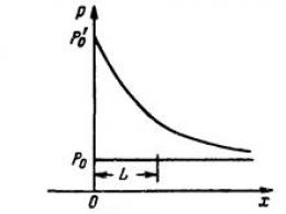
L - estimated span length, equal to half the sum of the lengths of spans adjacent to the calculated support, m;
C f \u003d 200 N - load from the weight of half of the fixation assembly.
Horizontal load on the support under the action of wind on the wires:

where H i j - wire tension, N/m;
R - curve radius, m.
Load on the support from a change in the direction of the wire when it is withdrawn to the anchorage

where a is a zigzag on a straight section of the path, m.
Total bending moment relative to the heel of the console
| (6.8) |
Let's calculate the loads on the intermediate support on the straight section
Gkpod \u003d 29.93 * 70 + 150 + 200 \u003d 2445
Gcons \u003d 24 * 9.8 \u003d 235.2
Load from the bracket on the field side, N/m
Gpdpr \u003d 1.72 * 70 \u003d 120.8
Rdpr \u003d 5.52 * 70 \u003d 387.06
Horizontal load on the support under the action of wind on the wires of the CS
PNT=6.72*70=470.8
Pkp \u003d 8.39 * 70 \u003d 587.3
Surface area affected by the wind
Sop=(9.6*(0.3+0.4))/2=3.36
Pop=0.615*0.7*25 2 *3.36=904.05
Let's calculate the moments
M og \u003d 9.27 * 387.05-120.8 * 0.6-401.8 * 0.5 + 235.2 * 1.8 + 9 * 470.8 + 2 * 7 * 587.3 + + 0.5*904.05*9.6+3.3*2445.2=28607.6 Nm
M op \u003d (9.27-6.75) * 387.05-120.8 * 0.6-401.8 * 0.5 + 235.2 * 1.8 + (9-6.75) * 470.8 +2*(7-6.75)*587.3+0.5*904.05*(9.6-6.75)+3.3*2445.2=8672.1 Nm
Table 6.1
In ice mode with wind, the moment is greatest. According to this moment, we select the support, provided that it should be less than the standard moment. We select the support SS 136.6-2 with a standard moment = 59000 N. Calculations for the remaining supports are made on a computer.
CONCLUSION
In the course of work on the design of the contact network of a given section, the load on the wires of the contact network was calculated (for the main track gк=8.73 N/m; gn=10.47 N/m; g=29.9 N/m) for the given climatic, wind and ice regions, the results are summarized in table 1.1. Based on the calculated loads, the permissible span lengths were determined (Table 2.1), plans for the contact network of the station and the span were developed. We completed the plan of the station contact network: we prepared the plan of the station, outlined the places for fixing the contact wires, placed supports in the middle of the station and at its ends, placed zigzags, traced anchor sections at the station, power lines, selected supporting and supporting structures. We also completed the plan for the contact network of the haul: we prepared a plan for the haul, completed the breakdown of supports and anchor sections, placed zigzags, and made a choice of types of supports. Completed the processing of plans for the contact network and compiled the necessary specifications.
Based on the calculated loads and span lengths, a mechanical calculation of the 1st track of section "a" was made. With its help, the design mode was determined - the mode of ice with wind, i.e. the greatest tension of the carrier cable occurs at a temperature of -5 for this area. Using the calculation, assembly curves were built for the construction of a contact network. After that, the loads from the wires and the wind loads on the support were calculated in three modes. According to the largest bending moment, the support SS 136.6-2 with a standard bending moment of 59000 N was chosen.
It was proved that at the station, when passing the contact suspension under the pedestrian bridge, the best way was to pass under the ASSO without fastening to it.
During the design, most of the calculations were carried out on a computer, which reduced the time of calculations and made them more accurate.
We are designing in order to increase the throughput and change diesel traction to electric, which is much cheaper.
LITERATURE
1. A.V. Efimov, A.G. Galkin, E.A. Polygalova, A.A. Kovalev. Contact networks and power lines. - Yekaterinburg: UrGUPS, 2009. - 88s.
2. Markvart K. G. Contact network. M: Transport, - 1977. - 271s.
3. Freifeld A. V., Brod G. N. Design of a contact network.
M .: Transport, - 1991. - 335s.
EXPLANATORY NOTE.
The guidelines are intended for full-time and part-time students of the Saratov College of Railway Transport - a branch of SamGUPS, specialty 13.02.07 Power supply (by industry) ( railway transport). The guidelines are drawn up in accordance with the work program of the professional module PM 01. Maintenance of equipment of electrical substations and networks.
As a result of the practical work on the MDK 01.05 "Construction and maintenance of the contact network", the trainee must:
acquire professional competencies:
PC 1.4. Maintenance of switchgear equipment of electrical installations;
PC 1.5. Operation of overhead and cable power lines;
PC 1.6. Application of instructions and regulations in the preparation of reports and the development of technological documents;
have general competencies:
OK 1. Understand the essence and social significance of your future profession, show a steady interest in it;
OK 2. Organize their own activities, choose standard methods and methods for performing professional tasks, evaluate their effectiveness and quality;
OK 4. Search and use the information necessary for the effective implementation of professional tasks, professional and personal development;
OK 5. Use information and communication technologies in professional activities;
OK 9. Navigate in conditions of frequent change of technologies in professional activity;
have practical experience:
Software 1. drawing up electrical diagrams of devices of electrical substations and networks;
Software 4. Maintenance of switchgear equipment of electrical installations;
Software 5. operation of overhead and cable power lines;
be able to:
5 to monitor the condition of overhead and cable lines, organize and carry out work on their maintenance;
9 use normative technical documentation and instructions;
know:
Conditional graphic designations of elements of electrical circuits;
The logic of constructing circuits, typical circuit solutions, schematic diagrams of operated electrical installations.
Types and technologies of work on maintenance of switchgear equipment;
The design of the contact network of the station is a complex process and requires a systematic approach to the implementation of the project using the achievements of modern technology and best practices, as well as using computer technology.
The guidelines deal with the issues of determining the distributed loads on the carrier cable of the contact suspension, determining the length of the equivalent span and the critical one, determining the values of the tension of the carrier cable depending on temperature, and constructing mounting curves.
According to the given scheme of the station, it is required:
1. Calculation of distributed loads on the catenary suspension cable for the main and side tracks.
4. Determination of the size of the sag of the contact wire and the carrier cable for the main track, with the construction of curves. Calculation of the average string length.
5. Organization of safe work.
Individual assignments for the implementation of practical work are issued immediately before execution, in the classroom. The time to complete each practical work is 2 academic hours, the time to defend the work done is 15 minutes included in the total time.
General guidance and control over the progress of practical work is carried out by the teacher of the interdisciplinary course.
PRACTICE #1
SELECTION OF PARTS AND MATERIALS FOR CONTACT NETWORK NODES
Purpose of the lesson: learn how to practically select parts for a given chain suspension.
Initial data: type and node of the catenary contact suspension (set by the teacher)
Table 1.1


Table 1.2
When choosing a support node and determining the method of anchoring the wires of a chain contact suspension, it is necessary to take into account the speed of trains in this section and the fact that the higher the speed of trains, the greater the elasticity of the chain contact suspension.
Contact network fittings are a set of parts designed for fastening structures, fixing wires and cables, assembling various nodes of the contact network. It must have sufficient mechanical strength, good conjugation, high reliability and the same corrosion resistance, and for high-speed current collection, it must also have a minimum mass.
All parts of contact networks can be divided into two groups: mechanical and conductive.
The first group includes parts designed only for mechanical loads: wedge and collet clamps for the carrier cable, saddles, fork thimbles, split and continuous lugs, etc.
The second group includes parts designed for mechanical and electrical loads: collet clamps for joining the carrier cable, oval connectors, butt clamps for contact wire clamps, string, string and adapter clamps. According to the material of manufacture, reinforcement parts are divided into: cast iron, steel, non-ferrous metals and their alloys (copper, bronze, aluminum).
Products made of cast iron have a protective anti-corrosion coating - hot-dip galvanizing, and steel products - electrolytic galvanizing followed by chromium plating.


Fig.1.1 Anchoring of a compensated catenary catenary for AC (a) and DC (b) current.
1- Anchor guy; 2- anchor bracket; 3,4,19 - a compensator cable with a steel diameter of 11 mm, a length of 10.11, and 13 m, respectively; 5- compensator block; 6- rocker; 7- rod "eye-double eye" 150 mm long; 8- adjusting plate; 9- insulator with a pestle; 10- insulator with an earring; 11- electrical connector; 12- rocker with two rods; 13.22 - clamp, respectively, for 25-30 loads; 14- limiter for garlands of goods single (a) and double (b); 15- reinforced concrete cargo; 16- cable limiter loads; 17 cargo limiter bracket; 18- mounting holes; 20 - rod "pestle-eye" 1000 mm long; 21- rocker for attaching two contact wires; 23 - bar for 15 loads; 24 - limiter for a single garland of goods; H0 is the nominal height of the contact wire suspension above the level of the rail head; bM is the distance from the loads to the ground or foundation, m.


Rice. 1.2 Anchoring of a semi-compensated AC chain suspension with a two-block compensator (a) and DC with a three-block compensator (b).
1- guy anchor; 2- anchor bracket; 3- rod "pestle-eye" 1000 mm long; 4- insulator with a pestle; 5- insulator with an earring; 6- compensator cable with a steel diameter of 11 mm; 7- compensator block; rod "pestle-eye" 1000 mm long; 9- bar for cargo; 10- reinforced concrete cargo; 11- limiter for a single garland of goods; 12- cable limiter loads; 13- bracket for load limiter; 14- compensator cable with steel diameter 10 mm, length 10 m; 15- clamp for cargo; 16- limiter for a double garland of goods; 17- rocker for anchoring two wires.

Fig. 1.3 Average anchoring of compensated (a-d) and semi-compensated (e) contact hangers for a single contact wire (b), double contact wire (d), fastening of the supporting cable and the middle anchoring cable on an insulated console (c) and on an uninsulated console (e).
1- main carrier cable; 2- cable of the middle anchoring of the contact wire; 3- additional cable; 4-pin wire; 5 - connecting clamp; 6- middle anchoring clamp; 7- console isolated; 8 - double saddle; 9- middle anchoring clamp for mounting on a carrier cable; 10- insulator.

Rice. 1.4 Attachment of the carrying cable to the non-insulated console.

Rice. 1.5 Fastening the carrier cable to a rigid cross member: a - general view with a fixing cable; b - with a fixing stand; and - a triangular suspension with brackets.
1-support; 2- crossbar (crossbar); 3- triangular suspension; 4- cable fixing; 5- locking stand; 6- retainer; 7- rod with a diameter of 12 mm; 8- bracket; 9- earring with pestle; 10 - hook bolt.
Execution order.
1. Select a support node for a given catenary and sketch it with all geometric parameters (Fig. 1.1, 1.2, 1.3,)
2. Select the material and cross-section of wires for simple and spring strings of the support node.
3. Select using fig. 1.1, 1.2, 1.3, 1.4, 1.5, details for a given node, the name and characteristics of which must be entered in table. 1.3.

Table 1.3
4. Apply a part for joining the contact wire and connecting the carrier cable, which are also entered in the table. 1.3.
5. Describe the purpose and location of the longitudinal and transverse connectors.
6. Describe the purpose of non-isolating mates. Draw a diagram of a non-isolating interface and indicate all the main dimensions.
7. Issue a report. Draw conclusions.
Federal Agency for Railway Transport.
Irkutsk State University of Communications.
Department: EZhT
COURSE PROJECT
Option-83
Discipline: "Contact networks"
"Calculation of the section of the contact network of the station and the stage"
Completed by: student Dobrynin A.I.
Checked: Stupitsky V.P.
Irkutsk
Initial data.
1. Characteristics of the chain suspension
On the main tracks of the haul and the station, the chain suspension is semi-compensated.
With two contact wires, the distance between them is assumed to be 40 mm.
Contact suspension type: M120 + 2 MF - 100;
Type of current: constant;
2. Meteorological conditions
Climatic zone: IIb;
Wind area: I;
Glacial area: II;
Ice has a cylindrical shape with a density of 900 kg/m 3 ;
Temperature of ice formations t = -5 0 С;
The temperature at which the wind of maximum intensity is observed t = +5 0 C;
3. Station
All tracks are electrified at the station, except for the access to the traction substation. Turnouts adjacent to the main track are marked 1/11 (there is one meter of lateral deviation per eleven meters of the track), the rest of the turnouts are marked 1/9.
The numbers on the diagram indicate the distances from the axis of the passenger building (in meters) to the arrowheads, entrance traffic lights, dead ends and pedestrian bridges, as well as the distances between adjacent tracks.
4. Driving
The span is specified as a stationing of the main objects: input signals, curves with corresponding radii, bridges and other artificial structures. The compatibility of the run with the station is checked by the stationing of the total input signal.
Picketing of the main objects of the haul
Input signal of a given station 23 km 8+42;
Beginning of the curve (center left) R = 600 m 2 + 17;
End of curve 5+38;
Axis of a stone pipe with a hole 1.1 m 5+94;
Beginning of curve (right center) R = 850 m 7+37;
End of curve 25 km 4+64;
Bridge over the river with a ride below:
bridge axle 7+27;
bridge length, m 130;
The axis of the reinforced concrete pipe with a hole of 3.5 m 9+09;
Curve start (center left) R = 1000 m 26 km 0+22;
End of curve 4+30;
Input next station 27 km 7+27;
Crossing axis 6 m wide 7+94;
The first arrow of the next station is 9+55.
1. The height of the bridge across the river is 6.5 m (the distance from the UGR to the lower part of the wind ties of the bridge);
2. On the right, along the course of kilometers, it is planned to lay the second track;
3. At a distance of 300 m on both sides of the bridge over the river, the path is located on an embankment 7 m high.
Introduction
The totality of devices, from generators of power plants to the traction network, constitutes the power supply system for electrified railways. From this system, in addition to their own electric traction (electric locomotives and electric trains), as well as all non-traction railway consumers and consumers of adjacent territories are fed with electrical energy. Therefore, the electrification of railways solves not only the transport problem, but also contributes to the solution of the most important national economic problem - the electrification of the whole country.
The main advantage of electric traction over autonomous traction (having energy generators on the locomotive itself) is determined by centralized power supply and boils down to the following:
The production of electrical energy at large power plants leads, like any mass production, to a decrease in its cost, an increase in efficiency and a decrease in fuel consumption.
Power plants can use any type of fuel and, in particular, low-calorie - non-transportable (the cost of transportation of which is not justified). Power plants can be built directly at the place of fuel extraction, as a result of which there is no need to transport it.
For electric traction, hydropower and the energy of nuclear power plants can be used.
With electric traction, energy recovery (return) is possible during electric braking.
With a centralized power supply, the power required for electric traction is practically unlimited. This makes it possible in certain periods to consume such power that cannot be provided by autonomous locomotives, which makes it possible to realize, for example, significantly higher travel speeds on heavy lifts with large train weights.
An electric locomotive (electric locomotive or electric wagon), unlike autonomous locomotives, does not have its own power generators. Therefore, it is cheaper and more reliable than an autonomous locomotive.
On an electric locomotive there are no parts operating at high temperatures and with reciprocating motion (as on a steam locomotive, diesel locomotive, gas turbine locomotive), which determines the reduction in the cost of repairing the locomotive.
The advantages of electric traction created by centralized power supply require the construction of a special power supply system for its implementation, the costs of which, as a rule, significantly exceed the costs of electric rolling stock. The reliability of the operation of electrified roads depends on the reliability of the power supply system. Therefore, the issues of reliability and efficiency of the power supply system significantly affect the reliability and efficiency of the entire electric railway as a whole.
Contact network devices are used to supply electricity to the rolling stock.
The contact network project, which is one of the main parts of the railway section electrification project, is carried out in compliance with the requirements and recommendations of a number of guiding documents:
Instructions for the development of projects and estimates for industrial construction;
Temporary instructions for the development of projects and estimates for railway construction;
Norms of technological design of electrification of railways, etc.
At the same time, the requirements given in the documents regulating the operation of the contact network are taken into account: in the rules for the technical operation of railways, the rules for maintaining the contact network of electrified railways.
In this course project, a section of the contact network of single-phase direct current was calculated. Installation plans for the contact network of the station and the haul were drawn up.
Contact network devices include all contact suspension wires, supporting and fixing structures, supports with parts for fastening in the ground, overhead line devices - wires of various lines (supply, suction, for power supply of automatic blocking and other non-traction consumers, etc.) and structures to mount them on supports.
The devices of the contact network and overhead lines, being exposed to various climatic factors (significant temperature fluctuations, strong winds, ice formations), must successfully withstand them, ensuring the uninterrupted movement of trains with established weight norms, speeds and intervals between trains at the required traffic sizes. In addition, under operating conditions, wire breaks, current collector shocks and other influences are possible, which must also be taken into account in the design process.
The contact network does not have a reserve, which leads to increased requirements for the quality of its design.
When designing a contact network in the section of the electrification project of the railway section, the following is established:
Design conditions - climatic and engineering-geological;
Type of contact suspension (all calculations to determine the required cross-sectional area of the wires of the contact network are performed in the power supply section of the project);
The length of the spans between the supports of the contact network in all sections of the route;
Types of supports, methods of fixing them in the ground and types of foundations for those supports that need them;
Types of supporting and fixing structures;
Power schemes and sectioning;
Scope of work on the installation of supports on hauls and stations;
Basic provisions for the organization of construction and operation.
Initial data analysis
With a double contact wire, a compensated contact suspension is used in sections with a train speed of 120 km / h or more. On the main tracks of the station, due to a decrease in speeds, as a rule, a semi-compensated chain suspension is used. Based on these meteorological conditions, we select the main climatic parameters that repeat once every ten years:
Temperature range from table. 2.s3: -30 0 С ¸ 45 0 С;
The maximum wind speed from the table. 5.s14: vnor = 29 m/s;
The wall thickness of the ice from the table. 1.c12: b =10 mm;
Depending on the operating conditions and the nature of the electrified section, the necessary correction factors for wind gustiness and ice intensity are selected. For the general case, we take their values of 0.95, 1.0, and 1.25, respectively, for the station, span, and embankment.
Determination of the loads acting on the wires of the contact network
For station and haul.
Calculation of vertical loads
The most unfavorable operating conditions for individual structures of the contact network can occur with various combinations of meteorological factors, which can consist of four main components: minimum air temperature, maximum intensity of ice formations, maximum wind speed and maximum air temperature.
The load from its own weight of 1 m of the catenary is determined from the expression:
where is the load from the own weight of the carrier cable, N / m;
The same but contact wire, N/m;
The same, but from strings and clamps, is taken equal to 1
Number of contact wires.
In the absence of data in the reference book, the load from the dead weight of the wire can be determined from the expression:
![]() , N/m (2)
, N/m (2)
where is the cross-sectional area of the wire, m 2;
Wire material density, kg/m3;
Coefficient taking into account the construction of the wire (for a solid wire =1, for a multi-wire cable =1.025);
For combined wires (AC, PBSM, etc.), the load from their own weight can be determined from the expression:
where , - cross-sectional area of wires from materials 1 and 2, m 2;
Density of materials 1 and 2, kg/m3.
For suspension M120 + 2 MF - 100:
![]()
According to expression (1) we get:
The load from the weight of ice, per one meter of wire or cable with a cylindrical form of its deposition, is determined by the formula:
where is the density of ice 900 kg / m 3;
Ice layer wall thickness, m
Wire diameter, m
Given that the product is 9.81×900×3.14 = 27.7×10 3 , we can write:
The calculated value of the thickness of the ice layer is defined as , where is the thickness of the ice layer in accordance with the ice area b = 10 mm; K G - coefficient taking into account the actual diameter of the wire and the height of its suspension. For the station and the haul K G =0.95.
According to expression (5), we determine the weight of ice per 1 m of the carrier cable


The thickness of the ice wall on the contact wire, taking into account its removal by the operating personnel and current collectors, is reduced by 50% compared to the carrying cable. The calculated diameter of the contact wire is taken as an average of the height and width of its cross section:
where H is the height of the wire section, m; A is the width of the wire section, m;
Using expression (6) we get:
![]() mm.
mm.
Using expression (5), we determine the weight of ice per 1 m of the contact wire


The weight of ice on the strings is not taken into account. Then the total weight of 1 m of the chain suspension with ice is determined by the formula:
where g is the weight of the catenary, N/m;
g GN - ice weight per 1 m of the carrier cable, N/m;
g GK - ice weight per 1 m of contact wire, N/m.
According to expression (7), the total weight of 1 m of the chain suspension with ice:
We determine the horizontal loads.
The wind load on the wire in the maximum wind mode is determined by the formula:
![]() (8)
(8)
where is the density of air at a temperature of t = +15 0 С and atmospheric pressure of 760 mm Hg. It is taken equal to 1.23 kg / m 3;
v Р - estimated wind speed, m/s; v P = 29 m/s.
C X - aerodynamic drag coefficient, depending on the shape and position of the surface of the object, for the station and the stage C X =1.20 for one wire C X = 1.25;
K V is a coefficient that takes into account the actual diameter of the wire and the height of its suspension. For the station and the haul, K B = 0.95.
d i - wire diameter (for contact wires - vertical section size), mm.


The wind load on the wire in the presence of ice on the wire is determined by the formula:
where is the calculated wind speed with ice (according to Table 1.4), m/s;
For determination on the contact wire, the value is assumed to be b/2.


We determine the resulting loads on n/t for two modes.
The resulting loads on a separate wire in the absence of ice:


In the presence of ice:


Calculation of span lengths
Wire tension calculation
The maximum allowable tension of the carrier cable is determined by the formula
where is the coefficient taking into account the spread of the mechanical characteristics of individual wires, 0.95;
Tensile strength of the wire material, Pa;
safety factor ;
S - calculated cross-sectional area, m2.

The maximum allowable and nominal tension for wires in table.10.

![]()
Determining the maximum allowable span lengths

where K is the tension of the contact wire, N;
Equivalent load on the contact wire from the carrier cable, N/m.
where is the permissible deviation of the contact wire from the axis of the path. On a straight section 0.5 m, on a curve 0.45 m;
Zigzags of the contact lead on adjacent supports. On a straight section of the track +/-0.3 m. On a curve +/-0.4 m.
Support deflection under the action of wind at the level of the carrier cable and contact wire. These values (depending on wind speed) are given on page 48.
Zigzag contact wire, the same size on adjacent supports.
Let's take zigzags on adjacent supports on a straight section directed in one direction, and on a curve in different directions.


where is the tension of the carrier cable in the wind mode of maximum intensity, N;
Span length, m;
The height of the string of insulators. We accept 4 PS-70E in the project. The height of one cup is 0.127 m.
The average length of the string in the middle of the span at the design height h0, m.


Calculation for a straight section of the track at the station (side tracks):

The resulting length differs from the previous calculation by less than 5 m, therefore, it can be considered finally accepted.


The resulting length differs from the previous calculation by less than 5 m, therefore, it can be considered finally accepted.

The resulting length differs from the previous calculation by less than 5 m, therefore, it can be considered finally accepted.
On a curved section of the path, the maximum allowable span length is determined from the expression:

The calculation of the maximum allowable span length is performed:
For a straight section: station (main and side track) and haul (plain and embankment);
For a curved section: on a stretch for a plain and an embankment with given curvature radii.


The resulting length differs from the previous calculation by less than 5 m, therefore, it can be considered finally accepted.


The resulting length differs from the previous calculation by less than 5 m, therefore, it can be considered finally accepted.

The resulting length differs from the previous calculation by less than 5 m, therefore, it can be considered finally accepted.


The resulting length differs from the previous calculation by less than 5 m, therefore, it can be considered finally accepted.

The resulting length differs from the previous calculation by less than 5 m, therefore, it can be considered finally accepted.


The resulting length differs from the previous calculation by less than 5 m, therefore, it can be considered finally accepted.
All calculations are summarized in a table
| Place of settlement | Span length without R e | Span length with R e | Final span length |
| 1. direct station and haul | 51.2 | 49.6 | 50 |
| 2. straight haul on the embankment | 45.2 | 43.8 | 45 |
| 3. curve R 1 =600m | 37.8 | 37.3 | 37 |
| 4. curve R 2 =850m | 42.3 | 41.8 | 42 |
| 5. curve R 3 =1000m | 44.4 | 43.8 | 44 |
| 6. curve R 6 =850m on embankment | 42.0 | 41.4 | 42 |
| 7. curve R 5 =1000 m on the embankment | 44.07 | 43.4 | 44 |
| 7. curve R4=600 m on embankment | 37.5 | 37.1 | 37 |
The procedure for drawing up a station and haul plan
The procedure for drawing up a station plan.
Station plan preparation. We draw the plan of the station at a scale of 1:1000 on a sheet of graph paper. The required length of the sheet is determined in accordance with the given scheme of the station, which indicates the distances of all the centers of turnouts, traffic lights, dead ends from the axis of the passenger building in meters. At the same time, we conditionally accept these marks to the left with a minus sign, and to the right with a plus sign.
We begin drawing the station plan with marking with thin vertical lines, every 100 meters of conditional station pickets in both directions from the axis of the passenger building, taken as a zero picket. Ways on the station plan are represented by their axes. On the arrows, the axes of the paths intersect at a point called the center of the turnout. Using the data on the given scheme of the station, we plot the axes of the tracks with parallel lines, while the distances between them must correspond to the given distances between the tracks on the accepted scale.
The station plan also shows non-electrified tracks. Having indicated the picket marks of the centers of turnouts on special outriggers, we draw turnout streets and exits. Next, we apply buildings, a pedestrian bridge, passenger platforms, a traction substation, entrance traffic lights, and crossings to the station plan.
Basting of places where it is necessary to fix contact wires.
We begin the layout of the supports at the station by marking the places where it is necessary to provide devices for fixing the contact wires. Such places are all turnouts over which the air switches must be mounted and all places where the wire must change its direction.
On single overhead switches, the best arrangement of the contact wires forming the switch is obtained if the fixing device is installed at a certain distance C from the center of the turnout. The displacement of the fixing supports is allowed to the center of the turnout by 1 - 2 meters and from the center of the turnout by 3 - 4 meters. At the vertex of the curve, we mark the fixing support along the picket of this vertex, while the zigzag at this support is always negative.
Arrangement of supports in the necks of the station
We start the breakdown of the supports at the station from the neck, where the largest number of places for fixing the contact wires are concentrated. From the planned places of fixation, we make a choice of those places where it is rational to install the bearing supports. At the same time, the actual span lengths should not exceed the estimated lengths, and the difference in the lengths of adjacent spans should not exceed 25% of the length of the larger one. In addition, supports on double-track sections should be located in one picket. If the installation of only load-bearing supports leads to a significant reduction in pickets, then the possibility of making some of the air arrows non-fixed should be considered.
Non-fixed aerial arrows can only be performed on side tracks, on supports located in the vicinity (up to 20 m) from the turnout.
Having chosen the dimensions of the spans between the supports fixing the air arrows of the main tracks, we proceed to the basting of the bearing supports at the next switches of the station, taking into account the requirements for the lengths of the spans listed above. We arrange zigzags at the fixing supports.
Arrangement of supports in the middle part of the station.
If there are artificial structures within the station, we choose the method of passing the contact suspension through these structures. In accordance with the accepted method, we outline the installation sites for the supports near the passenger building. After that, on the remaining parts of the station, if possible, using the maximum allowable spans, we outline the places for the supports of the rigid crossbars.
The procedure for passing the suspension under artificial structures at the station.
Artificial structures are found on hauls and stations of an electrified line, often do not allow passing a chain suspension of a normal type with normal dimensions.
The method of passing the contact wire under artificial structures is selected depending on the voltage in the contact network, the height of the artificial structure above the level of the top of the rail head (UHR), its length along electrified tracks, and the set train speed.
The placement of a contact wire under artificial structures with limited dimensions is associated with the solution of two main problems:
1. Providing the necessary air gaps between contact wires and grounded parts of artificial structures;
2. The choice of material, design and method of fixing the supporting devices.
The cross section of the contact wire within the artificial structure must be equal to the cross section of the contact wire in the adjacent areas, for which, if necessary, bypasses are installed to complete the cross section of the NT and reinforcing wires.
The slopes of the contact wire at the approaches to the artificial structure are set according to the conditions for the interaction of the current collector and the contact wire, depending on the maximum speed of movement and the parameters of the contact suspension and the current collector.
The minimum vertical space required to accommodate the current-carrying elements of the contact network during the passage of the suspension in the cramped conditions of existing artificial structures is 100 mm. with suspension without HT and 250mm. with NT.
In those cases when, at normal voltage in the contact network, it is impossible, according to the conditions of the necessary overall distances for this voltage, to place a contact suspension without reconstructing an artificial structure, an uninsulated contact suspension with a device on both sides of the neutral inserts is mounted within the artificial structure. Trains in this case are carried out through an artificial structure with the current turned off, by inertia.
In all cases, when the distance from the catenary wires to the grounded parts of artificial structures located above it, under the most unfavorable conditions, is less than 500 mm. at direct current and 650mm. with alternating current or there is any possibility of preloading the wires of the catenary suspension to parts of an artificial structure.
neutral element
 650 or less
chipper
insulators
Breakdown of anchor sections
After placing the supports along the entire length of the station, we make a breakdown of the anchor sections and finally select the installation sites for the anchor supports.
When laying out anchor sections, the following requirements and conditions must be met:
The number of anchor sections should be as small as possible. In this case, the length of the anchor section should not exceed 1600 meters;
In separate anchor sections we allocate side paths and exits between the main paths;
For anchoring, it is desirable to use previously planned intermediate supports;
When anchoring, the wire should not change its direction by an angle of more than 7 0;
If the length of the lateral path is more than 1600 meters, it should be divided into two anchor sections, and a non-isolating pairing should be performed in the middle.
The length of several spans located approximately in the middle of the anchoring section is reduced by 10% relative to the maximum in this place in order to place the middle anchorage.
Arrangement of supports at the ends of the station. According to the established sectioning scheme of the contact network, we perform longitudinal sectioning at the junction of the hauls to the stations. An isolating four-span interface is mounted between the input signal and the turnout of the station closest to the stage, if possible on straight sections of the track. At the same time, we reduce each transitional span by 25% of the calculated one; transitional supports along the first and second paths are shifted relative to each other by 5 meters.
The approach of the transitional support to the entrance traffic light is allowed at a distance of at least 5 meters.
After arranging the supports under the insulating junction, we divide the span between the extreme arrow and the junction, then arrange the zigzags, the direction of which must be consistent.
If there are supports at the crossing station, we position them so that the distance from the edge of the carriageway of the crossing along the course of the train to the supports is at least 25 meters.
To perform transverse sectioning from the power supply circuit and sectioning of the station, we transfer all sectional insulators and number them, and on the transverse cables of rigid crossbars we show mortise insulators between sections that are isolated from each other.
As the main type of load-bearing structures of the contact network at the stations, rigid crossbars covering from two to eight tracks should be taken. If more than eight tracks, flexible crossbars are allowed.
Power supply and sectioning of the contact network
Description of the scheme of supply and sectioning. On electrified railways, electric rolling stock receives electricity through a contact network from traction substations located at such a distance from each other to provide reliable protection against short circuit currents.
In a direct current system, electricity is supplied to the contact network alternately from two phases with a voltage of 3.3 kV and also returns along the track circuit to the third phase. Power alternation is performed to equalize the loads of individual phases of the power supply system.
As a rule, a two-way power supply scheme is used, in which each locomotive located on the line receives energy from two traction substations. The exception is the sections of the contact network located at the end of the electrified line, where a cantilever (one-sided) power supply scheme can be applied from the extreme traction substation and sectioning posts are arranged along the electrified line, insulating interfaces and each section receives electricity from different supply lines (longitudinal sectioning).
With longitudinal sectioning, in addition to separating the contact network at each traction substation and sectioning post, the contact network of each stage and station is separated into separate sections using insulating mates. The sections are interconnected by sectional disconnectors, each of the sections can be disconnected by these disconnectors. Through the feeder of the contact network Fl1, the span is fed from the western side of the station, located behind the insulating junction, which separates the main ways of the station from the span by an air gap.
The feeders are equipped with sectional disconnectors with motor drives TU and DU, normally closed.
The eastern span of the station is fed through feeder F2. The feeders are equipped with sectional disconnectors with motor drives TU and DU, normally closed.
The main tracks of the station are fed through the feeder Fl31. Equipped with sectional disconnector with motor drive TU and DU, normally closed.
Disconnectors A, B connect the station tracks and the haul, with motor drives on the technical specifications, they are normally switched on. With transverse sectioning at stations, the contact network of a group of tracks is separated into separate sections and fed from the main tracks through sectional disconnectors, which, if necessary, can be turned off. Sections of the contact network at the corresponding exits between the main and side tracks are insulated with sectional insulators. This achieves independent power supply for each track and each section separately, which facilitates the protection device and makes it possible, in case of damage or disconnection of one of the sections, to carry out the movement of trains along other sections.
Routing of supply and suction lines
We design the routes of supply and suction lines from the traction substation to the electrified tracks according to the shortest distance. For anchoring lines near the building of the traction substation and tracks, we use reinforced concrete supports.
Air supply and suction lines running along the station are suspended from the field side of the contact network supports. To transfer supply lines through the tracks, we use rigid crossbars on which T-shaped structures are mounted.
Tracing the contact network on the stage
Preparing a travel plan. We carry out the haul plan on a sheet of graph paper at a scale of 1: 2000 (sheet width 297 mm). The required length of the sheet is determined based on the given length of the stage, taking into account the scale of the required margin (800 mm) on the right side of the drawing for placing general data in the title block and is taken as a multiple of the standard size of 210 mm.
Depending on the number of tracks on the stage on the plan, we draw one or two straight lines (at a distance of 1 cm from each other), representing the axes of the tracks.
Pickets on the haul are marked with vertical lines every 5 cm (100 m) and numbered in the direction of kilometers counting, starting from the input signal picket specified in the task.
If, when tracing the contact network of the station, in the right neck there was a four-span insulating interface of the contact suspensions of the station and the haul, located before the input signal, then to repeat it on the haul plan, the numbering of the pickets must be started 2-3 pickets before the specified picket of the input signal. Above and below the straight lines representing the axes of the paths, we place the data in the form of tables along the entire span. Draw a straight line plan under the bottom table.
Using the marked pickets, in accordance with the task for the project, artificial structures are shown on the track plan, and on the straightened line plan we show kilometer marks, the direction, radius and length of the curved section of the track, the boundaries of the location of high embankments and deep recesses, we repeat the image of artificial structures.
The pickets of artificial structures, signals, curves, embankments, and excavations are indicated in the column "Stationage of artificial structures" of the lower table as a fraction, the numerator of which indicates the distance in meters to one picket, the denominator - to another. These numbers should add up to 100, since the distance between two normal pickets is 100 m.
Breakdown of the haul into anchor sections. We begin the arrangement of supports by transferring the insulating interfaces of the station to which the span adjoins to the plan of the haul of supports. The location of these supports on the haul plan should be linked to their location on the station plan. The linkage is carried out according to the input signal, which is indicated both on the station plan and on the haul plan as follows: determine the distance between the signal and the support closest to it using the marks on the station plan. This distance is added (or subtracted) to the picket mark of the signal and we get the picket mark of the support. Then we set aside from this support the lengths of the following spans indicated on the station plan, and we get the picket marks of the supports of the insulating interface on the haul plan. The picket marks of the supports are entered in the column "Stationage of the supports" of the bottom table. After that, we draw an insulating mate, since this is shown on the station plan, and arrange the zigzags of the contact wire.
Next, we outline the anchor sections of the contact network and the approximate location of their junctions. After that, in the middle of the anchor sections, we outline the approximate location of the middle anchorage places with that. In order to reduce spans with medium anchoring when laying out supports compared to the maximum estimated length in this section of the run.
When planning the anchor sections of the suspension, it is necessary to proceed from the following considerations:
the number of anchor sections on the stage should be minimal;
The maximum length of the anchor section of the contact wire on a straight line is taken to be no more than 1600 m;
· in sections with curves, the length of the anchor section is reduced depending on the radius and location of the curve;
If the length of the curve is not more than half the length of the anchor section (800 m) and is located at one end or in the middle of the anchor section, then the length of such an anchor section can be taken equal to the average length allowed for a straight line and a curve of a given radius.
At the end of the haul, there should be a four-span insulating junction separating the haul and the next station; the supports of such an interface already belong to the station plan and are not taken into account on the haul plan. Sometimes, in the initial data, a part of the span is specified for design, limited by the next four-span insulating junction. The supports of such a pairing refer to the haul plan.
We mark the approximate location of the junction supports of the anchor sections on the plan with vertical lines, the distance between which on a scale is approximately equal to three spans allowed for the corresponding section of the track. Then we outline with some conventional sign the location of spans with medium anchoring, and only after that we proceed to the arrangement of supports.
Arrangement of supports on the stage. The arrangement of supports is carried out by spans, if possible, equal to those allowed for the corresponding section of the track and terrain, obtained as a result of calculating the lengths of the spans.
Outlining the place of installation of supports. You should immediately enter their picketage in the appropriate column, indicate the lengths of the spans between the supports, and show the zigzags of the contact wires near the supports with arrows.
On straight sections of the track, zigzags (0.3 m) should be alternately directed at each of the supports to one side or the other from the axis of the track, starting from the zigzag of the anchor support, transferred from the plan of the station contact network. On curved sections of the path, the contact wires give zigzags in the direction from the center of the curve.
At the transition points from a straight section of the track to a curve, the zigzag of the wire at the support installed on the straight section of the track may be unrelated to the zigzag of the wire at the support installed on the curve. In this case, it is necessary to slightly reduce the length of one or two spans on a straight section of the track, and in some cases a span partially located on a curve, so that one of these supports can place a contact wire above the axis of the track (with a zero zigzag), and adjacent to it, make a zigzag of the contact wire in the right direction.
Zigzags of the contact wire at adjacent supports located on straight and curved sections of the track can be considered linked if most of the span is located on a straight section of the track and the zigzags of the contact wire at the supports are made in different directions or most of the span is located on a curved section of the track and zigzags are made one way.
The lengths of spans located partly on straight and partly on curved sections of the track can be taken equal to or slightly larger than the allowable lengths of spans for curved sections of the track. When laying out supports, the difference in the length of two adjacent spans of semi-compensated suspension should not exceed 25% of the length of the larger span.
In areas where ice formations are often observed and self-oscillations of wires may occur, the breakdown of supports should be carried out in alternating spans, one of which is equal to the maximum allowable, and the other is 7-8 m less. At the same time, avoiding the frequency of alternation of spans.
The spans with medium anchorings should be shortened: with semi-compensated suspension - one span by 10%, and with compensated - two spans by 5% of the maximum effective length in this place.
Selecting Supporting Devices
1. The choice of consoles.
Currently, non-insulated straight inclined consoles are used in alternating current sections.
The conditions for the use of non-insulated consoles in areas with an ice thickness of up to 20 mm and wind speeds of up to 36 m/s in AC sections are given in the table
Table
| support type | Installation location | Cantilever type with support dimensions | |||||
| 3,1-3,2 | 3,2-3,4 | 3,4-3,5 | |||||
| Intermediate | Straight | HP-1-5 | |||||
| Curve | NS-1-6.5 | ||||||
| Inner side | R<1000 м | ||||||
| R>1000 m | |||||||
| Outer side | R<600 м | HP-1-5 | |||||
| R>600 m | |||||||
| Transitional | Straight | HP-1-5 | |||||
| Support A | working | ||||||
| Anchored | NS-1-5 | ||||||
| Support B | working | HP-1-5 | |||||
| Anchored | NS-1-5 | ||||||
Console markings: NR-1-5 - uninsulated inclined console with stretched rod, bracket made of channels No. 5, bracket length 4730 mm.
NS-1-5 - uninsulated console with compressed rod, bracket made of channels No. 5, bracket length 5230 mm.
2. Choice of fixators
The choice of clamps is made depending on the type of consoles and the place of their installation, and for transitional supports, taking into account the location of the working and anchored branches of the suspension relative to the support. In addition, take into account which of them the latch is intended for.
In the designations of typical clamps, the letters F are used - a clamp, P - straight, O - reverse, A - contact wire of the anchored branch, G - flexible. The marking contains numbers characterizing the length of the main rod.
The choice of clamps is summarized in the table
Table
| Assignment of fasteners. | Types of clamps with dimensions of supports, m | ||||
| 3,1-3,2 | 3,2-3,3 | 3,4-3,5 | |||
| intermediate supports | Straight | Zigzag to support | FP-1 | ||
| Zigzag from a support | FO-II | ||||
| Outer side of the curve | R=300 m | FG-2 | |||
| R=700 m | UFP-2 | ||||
| R=1850 m | FP-II | ||||
| Inner side of the curve | R=300 m | UFO2-I | |||
| R=700 m | UFO-I | ||||
| R=1850 m | FOII-(3.5) | ||||
| transitional supports | Straight | working | FPI-I | ||
| Support A | |||||
| Anchored | FAI-III | ||||
| Support B | working | FOI-III | |||
| Anchored | FAI-IV | ||||
3. Choice of rigid crossbars.
When selecting rigid crossbars, the required length of the rigid crossbars is first determined.
L "= G 1 + G 2 + ∑ m + d op + 2 * 0.15, m
Where: G 1, G 2 - dimensions of the cross member supports, m
∑m is the total width of the track spans covered by the crossbar, m
d op \u003d 0.44 m - the diameter of the support in the damage of the rail heads
2 * 0.15 m - building permit for the installation of cross member supports.
I tabulate the choice of rigid crossbars
Table
4. Selection of supports
The most important characteristic of the supports is their bearing capacity - the permissible bending moment M 0 at the level of the conditional edge of the foundation. According to the bearing capacity and select the types of supports for use in specific installation conditions.
I summarize the choice of supports in a table
Table
| Installation location | support type | Rack brand |
| Straight | Intermediate | SO-136.6-1 |
| Transitional | SO-136.6-2 | |
| anchor | SO-136.6-3 | |
| Under the rigid crossbar (from 3-5 ways) | Intermediate | SO-136.6-2 |
| Under a rigid cross member (from 5-7 tracks) | Intermediate | SO-136.6-3 |
| anchor | SO-136.7-4 | |
| Curve | R<800 м | SO-136.6-3 |
Mechanical calculation of the anchor section of a semi-compensated suspension
For the calculation, we select one of the anchor sections of the main track of the station. The main purpose of the mechanical calculation of the chain suspension is the compilation of mounting curves and tables. The calculation is carried out in the following sequence:
1. Determine the calculated equivalent span by the formula:
where l i is the length of the i -th span, m;
L a is the length of the anchor section, m;
n is the number of spans.

Equivalent span for the first anchor section of the haul:

2. We set the initial design mode, in which the maximum tension of the carrier cable is possible. To do this, we determine the value of the critical span.
 (17)
(17)
where Z max is the maximum reduced suspension tension, N;
W g and W t min - reduced linear loads on the suspension, respectively, in ice with wind and at minimum temperature, N / m;
The temperature coefficient of linear expansion of the material of the carrier cable is 1/ 0 С.
The given values Z x and W x for the “X” mode are calculated by the formulas:
![]() , N;
, N;
 , N/m;
in the absence of horizontal loads q x = g x, the expression will take the form:
 , N/m;
in the complete absence of additional loads g x \u003d g 0 and then the reduced load will be determined by the formula:
 N/m; (eighteen)
Here g x , q x are, respectively, the vertical and resulting loads on the supporting cable in the “X” mode, N/m;
K - tension of the contact wire (wires), N;
T 0 - tension of the carrier cable with a weightless position of the contact wire, N;
j x - design coefficient of the chain suspension, determined by the formula:
 ,
,
![]()
The value "c" in the expression means the distance from the axis of the support to the first simple string (for a suspension with a spring cable, usually 8 - 10 m).
In a semi-compensated chain suspension, the contact wire has the ability to move when its length changes within the anchor section due to the presence of compensation. The carrying cable can also be considered as a loosely fixed wire, since the rotation of the string of insulators and the use of rotary consoles give it a similar possibility.
For freely suspended wires, the initial design mode is determined by comparing the equivalent L e< L кр, то максимальное натяжение несущего троса T max ,будет при минимальной температуре, а если L э >L cr, then the tension T max will occur when there is ice with wind. The correctness of the choice of the initial mode is checked by comparing the resulting load with ice q gn with the critical load q cr


The tension of the carrier cable with the deadweight position of the contact wire is determined under the condition that j x \u003d 0 (for spring suspensions), according to the formula:
 (19)
(19)
Here, the values with the index “1” refer to the mode of maximum tension of the carrier cable, and those with the index “0” refer to the mode of the free position of the contact wire. The index “n” refers to the material of the carrier cable, for example E n is the modulus of elasticity of the material of the carrier cable.

5. The tension of the unloaded carrier cable is determined by a similar expression:
 (20)
(20)
Here g n is the load from the own weight of the carrier cable, N / m.
The value of A 0 in is equal to the value of A 1 so there is no need to calculate A 0. Given different values of T px, the temperatures t x are determined. Based on the results of the calculations, we will construct mounting curves

The sag of the unloaded carrier cable at temperatures tx in real spans Li of the anchor section:

Rice. 3 Arrows of the sag of the unloaded carrying cable in real spans


7. The sag of the carrier cable F xi in the span l i is calculated from the expression:
 ,
,
 ; (22)
in the absence of additional loads (ice, wind) q x = g x = g, therefore, the reduced load in the case under consideration:
 ,
,
![]() ,
,
 ;
;  ;
;


Rice. 4 Arrows of a sag of the loaded bearing cable

Calculations of the tension of the supporting cable under modes with additional loads, where the values with index x refer to the desired mode (ice with wind or wind of maximum intensity). The results obtained are plotted on a graph.


8. The sag of the contact wire and its vertical movement at the supports for real spans is determined, respectively, by the formulas:
![]() , (23)
, (23)
where  ;
;
Here b 0i is the distance from the carrier cable to the spring cable against the support with the free position of the contact wire for a real span, m;
H 0 - spring cable tension, usually take H 0 \u003d 0.1T 0.
 (24)
(24)


Rice. 6 Arrows of contact wire sag in real spans under additional loads


The choice of the method of passage of catenary suspension in artificial structures
At the station:
Contact suspension passage under artificial structures, the width of which is no more than the interstring distance (2-12m), incl. under footbridges, can be carried out in one of three ways:
An artificial structure is used as a support;
The contact suspension is passed without fastening to an artificial structure;
An insulated insert is included in the carrying cable, which is attached to an artificial structure.
To select one of the methods, the corresponding condition must be met:
For the first case:

where is the distance from the level of the rail heads to the lower edge of the artificial structure;
The minimum allowable height of the contact wires above the level of the rail heads;
The largest sag of the contact wires with the sag of the carrier cable;
The minimum distance between the carrier cable and the contact wire in the middle of the span;
Maximum sag of the carrier cable;
Insulator string length:
Minimum sag of the carrier cable;
Part of the sag of the carrier cable at the minimum temperature at a distance from the closest approach to the artificial structure to the middle of the span;
Lifting of the carrier cable under the influence of the pantograph at a minimum temperature;
The minimum allowable distance between current-carrying and grounded parts;
Permissible distance from the contact wire to the fender.

Based on the results of this calculation, we come to the conclusion that in order to pass a contact suspension under a pedestrian bridge 8.3 meters high, in our case, it is necessary to use the third method: an insulated insert cuts into the supporting cable, which is attached to the bridge.
On the run:
Contact suspension on bridges with a downward ride and low wind braces is passed with the support cable attached to special structures installed above the wind braces. In this case, the contact wire is passed with fastening under wind ties with a reduced span length of up to 25 m. The height of the structure is selected from the expressions:
For semi-compensated suspension:

Bibliography
1. Markvardt K. G., Vlasov I. I. Contact network. - M .: Transport, 1997.- 271s.
2. Freifeld A. V. Design of a contact network. - M.: Transport, 1984, -397p.
3. Handbook of railway power supply. /Under the editorship of K.G. Marquardt - M .: Transport, 1981. - T. 2-392s.
4. Standards for the design of a contact network (VSN 141 - 90). - M.: Mintranstroy, 1992. - 118s.
5. Contact network. Assignment for a course project with guidelines-M-1991-48s.
Toolkit
To the implementation of practical exercises
On discipline "Contact network".
1. Selection of parts and materials for contact network nodes.
2. Determination of the loads acting on the wires of the contact network.
3. Selection of typical consoles and clamps for a given layout of supports.
4. Calculation of the bending moment acting on the support and selection of a typical intermediate support.
5. Registration of operational and technical documentation in the production of work on the contact network.
6. Registration of operational and technical documentation in the production of work on the contact network.
7. Checking the technical condition, adjusting and repairing the air arrow.
8. Checking the condition, adjustment and repair of the sectional insulator.
9. Checking the condition, adjustment and repair of the sectional disconnector.
10. Checking the condition, adjustment and repair of arresters of various types.
11. Checking the condition, adjusting and repairing the isolating interface ..
12. Mechanical calculation of the anchor section of the chain contact suspension.
13. Determination of the tension of the loaded carrier cable.
14. Calculation of the sag and the construction of mounting curves for the carrier cable and contact wire.
15. Drawing up a list of necessary materials, supporting and fixing devices for the contact network of the haul.
Explanatory note.
The methodological manual contains options for practical classes in the discipline "Contact Network". The purpose of the classes is to consolidate the knowledge gained in the theoretical course of the discipline, to acquire practical skills in checking the condition and adjusting individual nodes of the contact network, and skills in using technical literature. The topics of the proposed practical classes are chosen according to the work program of the discipline and the current standard of the specialty 1004.01 "Power supply in railway transport".
To perform classes in the "Contact Network" classroom, you must have the main elements of the contact network or their layouts, stands, the necessary posters, photographs, measuring and adjustment tools.
In a number of works, for better memorization and assimilation of the material, it is proposed to depict individual nodes of the contact network, describe their purpose and requirements for them.
When performing practical classes, students should use reference, regulatory and technical literature.
Attention should be paid to safety measures that ensure the safety of the maintenance and repair of contact network devices.
Practice #1
Selection of parts and materials for contact network nodes.
Purpose of the lesson: learn how to practically select parts for a given catenary contact suspension.
Initial data: type of chain contact suspension, chain contact suspension unit (set by the teacher according to tables 1.1, 1.2).
Table 1.1. Types of contact suspensions.
| Variant number | carrier cable | contact wire | current system | suspension type |
| side path | ||||
| - | PBSM-70 | MF-85 | constant variable | COP 70 |
| Main way | ||||
| M-120 | BrF-100 | constant | KS 140 | |
| M-95 | MF-100 | constant | KS 160 | |
| M-95 | 2MF-100 | constant | KS 120 | |
| M-120 | 2MF-100 | constant | KS 140 | |
| M-120 | 2MF-100 | constant | KS 160 | |
| PBSM-95 | NLF-100 | variable | KS 120 | |
| M-95 | BrF-100 | variable | KS 160 | |
| PBSM-95 | BrF-100 | variable | KS 140 | |
| M-95 | MF-100 | variable | KS 160 | |
| PBSM-95 | MF-100 | variable | KS 140 |
Table 1.2. Knot of a chain contact suspension bracket.
Brief theoretical information:
When choosing a support unit for a chain contact suspension and determining the method of anchoring the wires of a chain contact suspension, it is necessary to take into account the speed of trains in this section and the fact that the higher the speed of trains, the greater the elasticity of the chain contact suspension.
The fittings of contact networks is a complex of parts intended for fastening structures, fixing leads and cables, assembling various nodes of the contact network. The fittings must have sufficient mechanical strength, good conjugation, high reliability and the same corrosion resistance, and for high-speed current collection - also a minimum weight.
All parts of contact networks can be divided into two groups: mechanical and conductive.
The first group includes parts designed for purely mechanical loads. It includes: a wedge clamp, a collet clamp for a carrier cable, saddles, fork thimbles, split and continuous lugs, etc.
The second group includes parts designed for mechanical and electrical loads. It includes: collet butt clamps for joining the carrier cable, oval connectors, butt clamps for contact wire, string, connecting and adapter clamps. According to the material of manufacture, reinforcement parts are divided into cast iron (ductile or gray cast iron), steel, non-ferrous metals and their alloys (copper, bronze, aluminum, brass).
Products made of cast iron have a protective anti-corrosion coating - hot-dip galvanizing, and steel products - electrolytic galvanizing followed by chromium plating.
The order of the practical lesson:
1. Select a support node for a given catenary and sketch it with all geometric parameters (L.1, p.80).
2. Select the material and cross-section of wires for simple and spring strings of the support unit.
3. Select parts for a given node using L.9 or L10 or L11.
Enter the selected details in table 1.3.
4. Select a part for joining the contact wire and connecting the carrier cable. Enter the selected details in table 1.3.
Table 1.3. Details for contact suspension units.
5. Describe the purpose and location of the longitudinal and transverse electrical connectors.
6. Describe the purpose of non-isolating mates. Draw a diagram of a non-insulating interface and indicate all the main dimensions.
7. Issue a report. Draw conclusions from the work done.
Control questions:
1. What loads are perceived by the details of the contact network?
2. What determines the choice of the type of support unit for a chain contact suspension?
3. What are the ways to make the elasticity of the catenary contact suspension uniform?
4. Why can materials that do not have high conductivity be used for carrying cables?
5. Formulate the purpose and types of medium anchors.
6. What determines the method of attaching the carrier cable to the supporting structure?
Fig.1.1. Anchoring of the compensated catenary catenary of variable ( a) and constant ( b) current:
1- guy anchor; 2- anchor bracket; 3, 4, 19 - compensator cable with a steel diameter of 11 mm, length, respectively, 10, 11, 13 m; 5- compensator block; 6- rocker; 7- rod "eye-double eye" 150 mm long; 8- adjusting plate; 9- insulator with a pestle; 10- insulator with earrings; 11- electrical connector; 12- rocker with two rods; 13, 22 - clamp, respectively, for 25-30 loads; 15- reinforced concrete cargo; 16- cable limiter loads; 17- bracket for load limiter; 18- mounting holes; 20 - rod "pestle-eye" 1000 mm long; 21- rocker for attaching two contact wires; 23 - bar for 15 loads; 24 - limiter for a single garland of goods. 
Fig. 1.2. Anchoring of a semi-compensated AC chain suspension with a two-block compensator ( a) and direct current with a three-block compensator ( b):
1- guy anchor; 2- anchor bracket; 3 - rod "pestle-double eye" 1000 mm long; 4- insulator with a pestle; 5- insulator with an earring; 6- compensator cable with a steel diameter of 11 mm; 7- compensator block; 8- rod "pestle - eye" 1000 mm long; 9- bar for cargo; 10- reinforced concrete cargo; 11- limiter for a single garland of goods; 12- cable limiter loads; 13- bracket for load limiter; 14 - compensator cable with steel diameter 10 mm, length 10 m; 15- clamp for cargo; 16- limiter for a double garland of goods; 17- rocker for anchoring two wires.

Fig.1.3. Average anchoring compensated ( hell) and semi-compensated ( e) chain contact hangers; for a single contact wire ( b), double contact wire ( G); on an isolated console ( in) and on a non-isolated console ( d).
Contact network devices
CS is a complex system consisting of many devices. Each of them performs its own individual function. According to the functionality, the requirements for individual elements of the CS also differ. General requirements relate to mandatory serviceability, compliance with quality standards, safety.
It is customary to refer to CS devices: all supporting and supporting structures, which are designed to ensure a reliable and stable position of the leading current elements of the CS, organized by the suspension method; details of fastening and fixing the COP along the COP supports or overhead lines on separate overhead line supports; cables supporting and auxiliary cables of different designs and for different purposes depending on the design requirements of the compressor station; the actual wires of the COP, which represent the main wire (it is called a contact wire), as well as wires for other purposes - reinforcing, suction, power, auto-blocker power. devices, power supply, etc. 
In the course of work, almost all elements of the CS are influenced by various factors. The largest share of this influence is occupied by natural environmental factors. The compressor station is outdoors throughout its entire working life, therefore it is constantly exposed to the influence of precipitation, wind, sudden changes in temperature, ice phenomena, etc. All these conditions adversely affect the state of the COP and its operation, causing a change in the length of the wires, the occurrence of sparking phenomena, el. arcs, the phenomenon of corrosion for supports and other metal elements. It is not possible to completely get rid of these phenomena, however, it is possible to improve the resistance of the network to the external environment by various technical and technological methods, as well as the use of durable and reliable materials in construction. 
The CS should give maximum resistance to external environmental factors, moreover, implement uninterrupted movement of the EPS along the line with established standards for weight, speed, schedule and interval between trains passing one after another.
Particular attention should be paid to the stability and reliability of the COP because, unlike other power supply lines, it does not provide for a reserve. That is, this means that if any of the elements of the COP fails, this will lead to a complete shutdown of the line. It will be possible to resume the movement of rolling stock only after the necessary repairs have been carried out and the supply has been restored.
2017 - 2018, . All rights reserved.