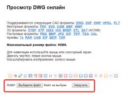
Summary: Modeling in ERwin. Building models in ERwin Features of building an er model when using erwin
6. Modeling in ERwin
ERwin's place information modeling
Building process information model consists of the following steps:
- definition of entities;
- determination of dependencies between entities;
- setting primary and alternate keys;
- definition of entity attributes;
- bringing the model to the required level normal form;
- transition to the physical description of the model: assignment of correspondences entity name - table name, entity attribute - table attribute; setting triggers, procedures, and constraints;
- database generation.
ERwin creates a visual representation (data model) for the problem being solved. This representation can be used for detailed analysis, refinement and dissemination as part of the documentation needed in the development cycle. However, ERwin is far from being just a drawing tool. ERwin automatically creates the database (tables, indexes, stored procedures, referential integrity triggers, and other objects needed to manage data).
Mapping the logical and physical layer of the data model in ERwin
There are two levels of representation and modeling in ERwin - logical and physical. The logical level means a direct display of facts from real life. For example, people, tables, departments, dogs, and computers are real objects. They are named in natural language, with any word separators (spaces, commas, etc.). At the logical level, the use of a specific DBMS is not considered, data types are not defined (for example, integer or real number) and no indexes are defined for the tables.
Target DBMS, object names and data types, indexes make up the second (physical) level ERwin models.
ERwin provides the ability to create and manage these two different presentation levels of a single diagram (model), as well as having many display options at each level.
ERwin Chart Components and Basic Chart Views
The ERwin diagram is built from three main blocks - entities, attributes and relationships. If we consider the diagram as graphic representation rules subject area, then entities are nouns and relationships are verbs.
The choice between the logical and physical level of display is carried out through the toolbar or menu. Within each of these levels, there are the following display modes:
- "Entity" mode - the name of the entity (for the logical model) or the name of the table (for the physical representation of the model) is displayed inside the rectangles; is used to conveniently view a large diagram or place entity rectangles on the diagram.
- The entity definition mode is used to present the diagram to other people.
- Attributes mode. When moving from the subject area to the model, it is required to enter information about what constitutes the entity. This information is entered by specifying attributes (on physical level- columns of tables). In this mode, the entity-rectangle is divided by a line into two parts - the attributes (columns) that make up the primary key are displayed in the upper part, and the rest of the attributes are displayed in the lower part. This mode is the main one when designing at the logical and physical levels.
- Mode " primary keys" - inside the rectangles - entities, only the attributes / columns that make up the primary key are shown.
- Icon mode. For presentational purposes, each table can be assigned an icon (bitmap).
- Verb phrase display mode. Link arcs show verb phrases linking entities (for the logical level) or foreign key names (for the physical level).
A chart can span more than one screen and more than one sheet when printed. In addition to scrolling the screen, for reviewing the model, there are modes of reducing / enlarging the image, displaying the entire model, displaying the selected part of the model.
Tools for creating a model in ERwin
The main tools for creating a model are available both from the menu and through the tool window. With their help, independent and dependent entities are created, identifying and non-identifying relationships, complete and incomplete categories, non-specific relationships and text elements.
Clicking the mouse over an entity enters one of the many ERwin editors:
- editors associated with the entity as a whole (entity definition, additional information, triggers, indexes, table characteristics, table-related stored procedures);
- attribute editors (attribute definition, table columns in the physical view of the model, 4GL tool repository, such as extended attributes in PowerBuilder).
Entity identification. Entities in ERwin
In the diagram, an entity is represented by a rectangle. Depending on the diagram's presentation mode, the rectangle may contain the name of the entity, its description, a list of its attributes, and other information.
The horizontal line of the rectangle divides the attributes of an entity into two sets - attributes that make up the primary key in the upper part and others (not included in the primary key) in the lower part.
An entity is a set of real or abstract objects, such as people, places, events, facts, that have General characteristics. Essence is a logical concept. The entity corresponds to a table in a real DBMS. In ERwin, an entity visually represents three main types of information:
- attributes that make up the primary key;
- non-key attributes;
- entity type (independent/dependent).
A primary key is an attribute or set of attributes that uniquely identifies an instance of an entity. If several sets of attributes can uniquely identify an entity, then the choice of one of them is carried out by the developer based on the analysis of the subject area.
For each primary key, ERwin creates a unique index when generating the database structure.
Instances of an independent entity can be uniquely identified without determining its relationships to other entities; a dependent entity, on the other hand, cannot be uniquely identified without determining its relationships to other entities. A dependent entity is displayed in ERwin as a rounded rectangle.
Relationships in ERwin
A relationship is a functional dependency between two entities (in particular, an entity may be associated with itself). For example, it is important to know the name of an employee, and it is equally important to know in which department he works. Thus, between the entities "department" and "employee" there is a relationship "consists of" (a department consists of employees). Relationship is a logical level concept that corresponds to a foreign key at the physical level. In ERwin, relationships are represented by five main pieces of information:
- connection type (identifying, non-identifying, complete/incomplete category, non-specific connection);
- parent entity;
- child (dependent) entity;
- communication power (cardinality);
- the admissibility of empty (null) values.
A relationship is called identifying if an instance of a child entity is identified through its relationship to the parent entity. The attributes that make up the primary key of the parent entity are included in the primary key of the child entity. A child entity in an identifying relationship is always a dependent entity.
A relationship is said to be non-identifying if an instance of a child entity is identified other than through a relationship with the parent entity. The attributes that make up the primary key of the parent entity are included in the non-key attributes of the child entity.
To define ERwin relationships, select the type of relationship, then click on the parent and child entities. An identifying relationship is shown as a solid line; non-identifying - dotted line. The lines end with a dot on the side of the child entity.
When a relationship is defined, the primary key attributes of the parent entity are migrated to the corresponding attribute area of the child entity. Therefore, such attributes are not entered manually.
Primary key attributes of the parent entity are migrated with their names by default. ERwin allows you to enter roles for them, i.e. new names under which the migrating attributes will be represented in the child entity. In the case of multiple migrations of an attribute, such a renaming is necessary. For example, the entity "intermediary transaction" has the attribute "code of the company-seller" and "code of the company-buyer". In this case, the primary key of the entity "enterprise" ("enterprise code") has two roles in the child entity.
At the physical level, the role name is the name of the foreign key column in the child table.
The cardinality of a link is the ratio of the number of instances of the parent entity to the corresponding number of instances of the child entity. For any relationship other than non-specific, this relationship is written as 1:n.
ERwin, in accordance with the IDEF1X methodology, provides 4 options for n, which are represented by an additional character in the child entity: zero, one or more (by default); zero or one; exactly N, where N is a specific number.
The admissibility of NULL values in non-identifying relationships ERwin depicts an empty diamond on the arc of the relationship from the side of the parent entity.
Power designations, respectively, zero, one or more, one or more, zero or one in IE notation are shown in Fig. one.
Fig.1. Link power notation in IE notation
The link name at the logical level is a "verb" linking entities. The physical name of the link (which may differ from the logical one) for ERwin means the name of the constraint (constraint) or index.
Graphical Model Editing
All objects of the ERwin model can be edited by means accepted in Windows - grouping, copying, deleting, moving, using the system buffer. Colors and fonts are set in convenient dialogs.
Model components represented by text (names of entities, attributes, text elements) can be edited directly on the screen.
Alternative Keys
An alternate key is an attribute (or group of attributes) that is different from the primary key and uniquely identifies an instance of an entity. For example, for the entity employee (employee ID, last name, first name, patronymic), the group of attributes "last name", "first name", "patronymic" can be an alternative key (assuming that full namesakes do not work at the enterprise).
For an alternative key, as well as for a primary one, ERwin automatically creates indexes when generating a database.
Inverted indices
The attributes that make up the alternate key unambiguously (uniquely) identify entity instances. In ERwin, you can also compose attribute groups that do not uniquely identify entity instances, but are often used to access data. For each such attribute group, ERwin creates non-unique indexes.
The same entity attributes can be included in several different key groups.
Attribute Unification
A dependent entity can inherit the same foreign key from more than one parent entity, or from the same parent entity through multiple relationships. Unless distinct roles are introduced for such multiple inheritance, ERwin considers the foreign key attributes to appear only once in the dependent entity.
Unification is the union of two or more foreign key attribute groups into one foreign key (attribute group), on the assumption that the values of the same-named attributes in the child entity are always the same.
Let's consider an example: the entity "employee" has the primary key "employee code" and is linked by an identifying relationship with the entities "spouse" and "children". In this case, the primary key is migrated to dependent entities. In turn, the "spouse" entity has a non-identifying relationship with the "children" entity. There are two key migration paths, however, in the children entity, the employee ID attribute appears once as an element of the primary key.
There are cases when the unification of attributes gives an incorrect result from the point of view of the subject area. To unify attributes, role names are entered.
Some entities define an entire category of objects of the same type. In ERwin, in this case, an entity is created to define the category and for each element of the category, and then a categorization relationship is entered for them. The parent entity of a category is called a supertype, and the children are called a subtype.
For example, the entity "employee" can contain data about both full-time employees and temporary employees. The first and second have different, partially overlapping sets of attributes (the minimum intersection of subtypes is the primary key). The common part of these attributes, including the primary key, is placed in the employee supertype entity.
The different part (for example, hourly pay data for temporary workers and salary and vacation data for full-time workers) are placed in subtype entities.
In the entity-supertype, a discriminator attribute is introduced, which makes it possible to distinguish between specific instances of the entity-subtype.
Depending on whether all possible subtype entities are included in the model, the categorical relationship is complete or incomplete. Continuing the example, if a supertype can contain data about laid-off employees, then this relationship is an incomplete categorization, since there is no entry for it in entities - subtypes.
In ERwin, a full category is represented by a circle with two underlines, and an incomplete category by a circle with one underline.
Implementing Referential Integrity with ERwin
Referential integrity is the enforcement of the requirement that the foreign key values of a child entity instance match the primary key values in the parent entity. Referential integrity can be controlled for all operations that change data (INSERT/UPDATE/DELETE). Referential integrity controls in ERwin include automatic generation of triggers and the use of declarative referential integrity mechanisms (for those DBMS that support these mechanisms).
For each connection at the logical level, requirements can be set for processing INSERT / UPDATE / DELETE operations for the parent and child entities. ERwin provides the following options for handling these events:
- lack of verification;
- validation;
- prohibition of the operation;
- cascading operation execution (DELETE/UPDATE);
- setting an empty (NULL value) or specified default value.
According to the selected option, ERwin automatically creates the necessary triggers in the SQL dialect of the target DBMS. At the same time, ERwin uses a library of trigger templates that can be modified.
When generating a database structure, referential integrity triggers can be overridden at three levels:
- Triggers can be overridden to provide rules for the entire model.
- The triggers specified for a particular relationship can be overridden.
- Triggers specified for a particular table can be overridden.
The override type is specified by the developer when generating the database schema (Fig. 6 - respectively RI Type Override, Relationship Override, Entity Override).
Storing Information in an ERwin Model
Typically, ERwin models are saved to disk as a file. It is possible to store the model in the target DBMS. To do this, using ERwin itself, an ERwin metabase is created in the target DBMS. Model information is stored in this database. In a particular case, the database can also be dBase files that ERwin works with via ODBC.
An example of model development in ERwin
Consider the development cycle using the example provided in Codd's article.
Let us briefly recall the content side of the problem. Employee records are maintained. For each employee, information is stored about the children and the list of positions held by this employee. For positions, information on established official salaries is stored.
First, let's create the logical level of the model. To do this, set the display mode for entities (Display/Entity Level). Using the toolbar, we will create the entities "employee", "children", "work history", "salary history". We will name entities in Russian.
After selecting each entity, we will set a detailed description for it in Russian in the "Entity Definition" editor. This description will appear in ERwin reports and can be displayed in a diagram.
Let's specify connections between entities. For example, "employee" has an identifying relationship "is a parent" to the entity "children". The description of the relationship is entered in the "Editor/Relationship" editor.
The result of the work is displayed on the ERwin diagram (Fig. 2).

Rice. 2. Entity level diagram
Now let's switch to the attribute setting mode (Display/Atribute Level). In the "Entity/Attribute" editor, let's set the names of key and non-key attributes in Russian. Note that for the child entity "children", the key attribute "employee number" is not specified manually. ERwin provides its migration from the parent entity. The same happens with other child entities.
For the "name" attribute of the "employee" entity, we indicate that it is an alternative key (we will assume that all employees have unique first / last names). To do this, after the attribute name, we place the pointer AK1 in brackets.
The result of the work is displayed on the ERwin diagram (Fig. 3) in IDEF1X notation.

Rice. 3. Attribute level diagram in IDEF1X notation
The view of the same diagram in IE (Information Engineering) notation is shown in Fig.4.

Rice. 4. Attribute Level Diagram in IE Notation
Since the names of attributes and entities were set by us in Russian, to go to the physical level of the model, they should be associated with identifiers of tables, columns, and constraints that satisfy the rules of the target DBMS (usually this means using Latin letters, numbers, and some special characters).
In the "Database Schema" editor, specify the corresponding table name for each entity. Then, in the "Attribute Definition" editor, we set the names of the columns of the tables corresponding to the attributes of the entities. ERwin also provides for the migration of column names to subordinate tables.
At this stage, you can also use the "Extended Attributes" editor to define PowerBuilder's extended attributes (display format, edit mask, control rule, alignment, headings, and comments).
The "Relationship Definitions" editor specifies the physical name of the relationship, which corresponds to the name of the constraint created by ERwin in the database.
Now everything is ready to create a database and you need to select the target DBMS (if this has not been done before). Let's choose, for example, Sybase System 10.
In the SYBASE Database Schema editor, we set the data types for the table columns.
The dialog in which the data type is selected is shown in Fig.5.

Rice. 5. Definition of the physical model
Now we can move on to creating the database. To do this, the "Sybase schema generation" command is executed. ERwin will build a database generation SQL package. Figure 6 shows the dialog for selecting the parameters for generating a package for generating a database. The figure shows that a filter can be set (generation of not all tables), a package of SQL statements can be viewed (preview), printed, saved to a file (report), and generated (generate).
Rice. 6. Selecting database generation options
7. Advanced features of ERwin
Reverse engineering
Reverse engineering, that is, restoring the information model from an existing database, is used when choosing the optimal platform (rightsizing) for an existing desktop database or a database on the mainframe, as well as when expanding (or modifying) an existing structure that was built without necessary supporting documentation. After the model recovery process is completed, ERwin automatically "spreads" the tables on the diagram. Now you can perform modifications already using the logical scheme - add entities, attributes, comments, links, etc. Upon completion of the changes, one command - synchronize the model with the database - updates all the changes made.
Model building can be performed both on the basis of the database catalog data and on the basis of the package SQL statements The with which the database was created.
Database Synchronization
In the process of developing an information system, a situation may arise when the database structure and the information model do not correspond to each other. ERwin provides an opportunity to bring them into line.
For this, a synchronization function with the database is provided. After connecting to the DBMS, a list of inconsistencies between the existing data structure and the model is offered. For example, if a new table is created in the database, then ERwin will offer to include it in the model. If a new table is added to the model, ERwin will offer to create it in the real database. Similarly, when adding columns to a database or model, ERwin offers to perform the appropriate synchronization operations. The procedure for selecting synchronized tables is shown in Figure 7.
Rice. 7. Selecting Synchronized Tables
ERwin "knows" about such features of data storage in individual DBMS as segments (in Sybase) and table space (in Oracle). Physical placement information can be included in the model and used in forward and reverse engineering.
Interfaces to DBMS
ERwin supports a direct interface with the main DBMS: DB2 versions 2 and 3, Informix versions 5.1, 6.0, 7.1, Ingres, NetWare SQL, ORACLE versions 6 and 7, Progress, Rdb versions 4 and 6, SQL/400 versions 2 and 3, SQLBase versions 5 and 6, SQL Server versions 4 and 6, Sybase version 4.2, Sybase System 10 and 11, Watcom SQL. Note that both the most modern and previous versions main DBMS (Fig. 8).
Rice. 8. Choosing a DBMS for creating a model
ERwin also supports desktop (desktop) DBMS: Microsoft Access, FoxPro, Clipper, dBASE III, dBASE IV and Paradox.
The design at the physical layer is done in terms of the database that is supposed to be used in the system. It is important that ERwin "knows" the correspondences between the capabilities of the DBMS of different vendors, as a result of which it is possible to convert the physical schema designed for one DBMS to another.
To create the physical structure of the database, the generation of a DDL script (data definition language) can be requested. This uses the SQL dialect for the selected server type and version. Although the generated code does not need to be modified, it is possible to save it to a file or print it.
Support for 4GL tools
ERwin is available in several different editions targeting the most common 4GL development tools. Supported tools include PowerBuidler by Powersoft, SQL Windows by Gupta, Visual Basic by Microsoft, Oracle*CASE by Oracle.
ERwin's bi-directional database interactions provide both back-end and client-side information management. For example, for PowerBuilder, you can view/edit extended attributes in ERwin editors.
ERwin's focus on 4GL tools allows you to set for future applications most of the parameters directly related to the database, already at the design stage of the information model.
Let's show the principles of organizing such interaction on the example of PowerBuilder.
PowerBuilder creates several internal tables in the database to store its repository (extended attributes for datawindow). The use of extended attributes ensures that the display style of the same database columns is maintained for all applications created. working group. Extended attributes set parameters such as display format, editing style, validation expression, initial value, alignment, display element width and height, edit form label, table display title.
The same synchronization operations are allowed for extended attributes as for the entire model, i.e. descriptions can be loaded into the database and, conversely, extended attribute definitions created from the PowerBuilder environment can be loaded from the database into ERwin for modification.
An example of defining extended attributes is shown in Figure 9.

Rice. 9. Setting PowerBuilder Extended Attributes
The ERwin function for generating DataWindow allows you to generate prototypes of data windows of a future application already at the stage of creating an information model. To create a Data Windows, a Wizard is offered, with the help of which the window style and the selected columns of the tables are specified.
Agreements
For the sake of brevity, we will adopt some conventions:
· Click - pressing the left mouse button.
Right click - click on right button mice.
Double click - two consecutive clicks on the mouse button
· Select - move the cursor to the corresponding object (diagram element, menu item, icon) and click the left mouse button.
Drag - select an object and, without releasing the mouse button, move the cursor v another position.
· An entry of type File/Open means that you need to select the File menu item, and then from the opened menu - the Open item.
ERwin desktop
On fig. 1 shows the desktop of the ERwin software product from Logic Works.
| |
| |
| |
| |
| |
Fig.1- Erwin desktop.
In figure 1, the numbers indicate:
1- main menu;
2- toolbar;
3- set of special tools;
4- panel of fonts and colors;
5- chart field.
Let's take a closer look at the components of the desktop.
The main menu contains general-purpose commands. Note that most of these commands are duplicated either by toolbar icons or right-click menu items. Therefore, we will focus now on commands related to general view desktop. The Window item has the following sub-items:
Toolbar - toolbar;
Font & Color Toolbar - panel of fonts and colors;
Statusbar - status bar;
ERwin Toolbox is a set of special tools.
If any of the listed items is not checked, then the corresponding item is not displayed on the desktop. The Option / Show Display Menu and Option / Show Editor Menu items add additional features to the main menu: Display and Editor.
The toolbar contains the following groups of icons:
Working with files:
Create a new diagram;
Open an existing diagram;
Submit the diagram for printing.
Note that these icons are duplicated by the commands of the File main menu item.
Model presentation levels:
Entity level;
Attribute level;
Description level;
Physical layer (if this icon is clicked, then the demonstration at the attribute level indicates their types).
These tools are duplicated by the Display menu item. It contains additional presentation levels: Primary Key Level - only primary keys are displayed, Physical Order Level - attributes are not divided into key and non-key ones.
Scaling:
Decrease;
Increase;
No magnification;
The smallest (further reduction will lead to unreadable scheme);
View part (after selecting this tool, select the fragment you want to view on the workspace).
All actions of this group are duplicated by the Display/ /Zoom item.
Working with the server:
Generate a script for the server;
Connect to the server;
Select server.
A set of special tools includes the icons necessary for the graphical construction of a data schema. It consists of the following tools:
Selecting an object;
Attribute manipulation;
Independent entity;
Dependent entity;
Full categorization;
Incomplete categorization;
One-to-many identifying relationship;
Non-identifying "one-to-many" relationship;
Many-to-many relationship;
Text label.
CONCEPT DESIGN
Creation of entities
Entities in a conceptual diagram can be dependent or independent. In the diagram, any entity is represented by a rectangle. Above it is the name of the entity. The rectangle is divided into two parts: the upper one is the area of the primary key; the lower one is the area of other attributes. When constructing an entity, the rectangle is initially empty, and the name has the form E/n (for example, E/1, E/2, etc.).
To build an independent entity, you need to click on the corresponding icon from the set of special tools, and then click on the diagram field in the place where the entity to be created should be located. To build a dependent entity, select the Dependent Entity tool and click on the diagram field. Note that the rectangle representing such an entity has rounded corners. When building a diagram, there is almost no need to directly specify dependent entities, since ERwin converts ordinary entities into dependent entities when linking or categorizing.
If the designer is not satisfied with the position of the entity on the field, then you need to select the “Point to Object” icon from the set of special tools and drag the entity to a new location. To delete the selected entity, use the Delete key on your keyboard. You can change the size of the rectangle depicting an entity by selecting the main menu item Option / Entity Size. The Option / Layout menu item is used to arrange the position of entities on the field.
Now let's define the name of the entity and its characteristic attributes. To do this, use the Entity-Attribute item from the right-click menu. Enter the name of the entity in the Entity Name field of the opened editor. Using a switch, you can change the dependency of an entity. The Primary Key edit field is intended for entering the names of the attributes that make up the primary key. Non-key attributes are entered in the Non-Key Attributes field. Note that in both cases, the Enter key on the keyboard is used to separate the attributes from each other. On fig. 2 shows an example of an independent entity.
Rice. 2 - Independent entity
To add an extended description of an entity (Definition) and a general view of all entities, use the Report / Entity Browser item.
In ERwin, it is possible to manipulate individual attributes. To do this, select the "Attribute Manipulation" icon. In this mode, you can:
· Delete attribute. To do this, select a separate attribute and press Delete on the keyboard.
· Move an attribute inside an entity. To do this, select the attribute and, without releasing the mouse button, move it to the desired location. Note that in this way you can move attributes both within the key and non-key areas, and between them.
· Move attributes between entities. The procedure for this action is similar to the previous one. If the Ctrl key is pressed while moving an attribute, it will be copied to another entity.
Building connections
Let's consider the construction of one-to-many relationships. To do this, select the appropriate icon from the set of special tools, then click sequentially on the parent and child. An identifying relationship is represented by a solid line and a black dot next to the rectangle representing the child. Such a relationship is characterized by the transfer of the primary key of the parent to the identifier of the child. On fig. 3 depicts a one-to-many identity relationship.
Fig.3. – Identification link
A non-identifying relationship is built in a similar way. It is represented by a dotted line and a diamond next to the rectangle representing the parent. Such a diamond means that the existence of the parent is optional, i.e. the foreign key field can be null. Building a non-identifying relationship in ERwin is characterized by moving the primary key of the parent to the non-key attributes of the child. Figure 4 shows a non-identifying relationship.
Rice. 4. - Non-identifying link
As noted, designing a many-to-many relationship results in a new entity. An example of building a relationship of this type between the entities first and second is shown in Fig. 5.
Rice. 5. - Many-to-many relationship
You can view and change the description of a relationship using the Relationship item from the menu that pops up by right-clicking on a relationship. The window that opens indicates:
· Communication name (Verb Phrase field).
· Relationship Type: identifying (Identifying) or non-identifying (Non-Identifying).
· Cardinality of communication (Cardinality). ERwin allows you to define the following types of relationships.
1. Zero, one or more. The presence of such a cardinality does not introduce additional designations into the diagram.
2. One or more. Such links are indicated by the letter P next to the rectangle representing the descendant.
3. Zero or one. Cardinality is denoted by the letter Z.
4. Set. In this case, the Exactly field must contain a number characterizing the cardinality. Such a relationship is indicated by a number next to the rectangle representing the child.
· Possibility of existence of Null - values (switch Nulls).
The role of the foreign key. In this case, the role name is written in the Role Name field. At the same time, the Foreign Key field of the editor contains the construction<имя роли>.<имя первичного ключа родителя>.
If the diagram does not display the names or cardinalities of the connection, then it is necessary to put pointers in front of the Display / Verb Phrase and Display / Cardinality items.
To delete a connection, select the "Point to object" icon, click on the corresponding connection and press Delete on the keyboard.
The division of entities into categories in ERwin is shown similarly in Fig. 6.
Rice. 6 - Full categorization
To build categories, do the following:
Fully describe the main entity;
Build entities-categories;
Select the icon for complete or incomplete categorization from a set of special tools;
Click on the main entity;
Click on one of the categories;
To build each subsequent category, click on the category sign, and then on the corresponding entity.
To remove the connection of one of the categories with the main entity, select the corresponding branch and press Delete on the keyboard. If you want to delete the entire categorization, point to the category sign and click Delete.
LOGIC DESIGN
Logical design begins with the choice of a data model. All DBMS that ERwin works with are relational, and this determines the choice of data model.
To select a specific DBMS, click the "Select Server" icon. In the window that opens, place the pointer in front of the selected DBMS, if necessary, set the version. In addition, you need to select the characteristics of the table fields (type and nullability) by default.
An important stage of logical design is the definition of a strategy for maintaining the integrity of information. To set the default strategy for various types links, click the Referential Integrity Default button in the DBMS selection window. ERwin offers three types of strategies:
1. Restrict - forbidding. It is characterized by the prohibition of actions with related entities.
2. Cascade - cascading. Such a strategy is to perform cascading operations on related entities.
3. Set Null - zero. This strategy is to set Null - the value of the field.
After choosing a DBMS, let's start describing the data in its terms. To do this, select from the menu that pops up by right-clicking on the entity, the item<имя выбранной СУБД>database schema. In the window that opens, you can specify the names of tables and their fields, as well as the characteristics of these fields.
In practice, it often happens that not all relationships of any type are defined by the same strategies for maintaining integrity constraints. To change the strategies for a specific link, use the Referential Integrity item from the menu that pops up by right-clicking on a link. If the diagram does not contain information about the selected strategies, place the pointer in front of the Display / Referenda Integrity item.
To generate a script for the selected DBMS, click the "Generate script for the server" icon. At the same time, ERwin builds a database schema according to certain tables. If the selected DBMS supports writing triggers, then they are built depending on the chosen strategies for supporting integrity constraints.
PHYSICAL DESIGN
At this design stage, we will add additional indexes to the resulting schema. To do this, use the<имя СУБД>Index of the menu that pops up on the right click on the entity. In the window that opens, click the New button to build a new index, then specify an attribute for it by clicking on the visual image of this attribute. Note that now general diagram the attributes on which the indexes are built are marked with the letters AK. This means that they are alternate keys.
EXERCISE
1. Build a conceptual database schema for a certification body using ERwin. Description of the subject area is given below.
The certification body is accredited to issue certificates for certain types of products. Each type of product is described by a code (according to the classifier), a type name (for example, dairy products) and a type (for example, milk). For each type of product, there may be several regulatory documents, and the effect of each regulatory document applies to several types of products. A normative document is characterized by a level (GOST, OST, etc.), number and name.
The certificate is issued only for one type of product and only for one client. The same client can apply to the certification body several times, so you need to store information about clients (organization code, name, address and phone number).
The client can apply to the certification body with one of two types of application for certification: an application or a declaration. Depending on this, different kinds internal documentation and various information is stored. (Table 1)
Table 1
In this case, the numbering of applications and declarations is end-to-end. This means that if there is an application under the number, then there should not be a declaration under this number.
The certification body stores information about its employees (personal code, surname, position and address). In addition, it is necessary to know what kind of work and on what application the employee performed. The work carried out on the application can be of four types: draw up an application, make a decision on the application, decide on the issuance of a certificate, issue a certificate. According to the same application, different types of work can be performed by different employees. In the conceptual scheme, there must be a breakdown into categories. In addition, foreign key roles must be used.
2. Convert the conceptual schema into tables of the selected DBMS using ERwin. Build triggers.
3. Create three users for the database with the following rights:
1) "Reports" - the right to read all the information (no other rights);
2) "References" - all rights to information about employees, customers, products and regulations;
3) "Documentation" - all rights to information about the internal documentation of the certification body and customers; the right to read product data and regulatory documents.
The report must contain:
Printout of the conceptual diagram from ERwin;
Justification of the choice of strategies for maintaining database integrity constraints;
Structure of tables and triggers;
Description of the means of creating base users.
CONTROL QUESTIONS
1. What types of connections can exist in the subject area?
2. How to remove the many-to-many relationship from the database schema?
3. What is the difference between identifying and non-identifying relationships?
4. In what cases does it become necessary to describe the roles of foreign keys?
5. How can you justify the selection of categories?
6. What is the difference between complete and incomplete division into categories?
7. What types of integrity constraint support strategies were used when performing laboratory work?
Bibliography
1. Date K.J. Introduction to database systems. - Proc. allowance: Translated from English. – 6th ed. - M. et al.: Williams, 2000. - 846 p.
2. Robinson S. Microsoft Access 2000: textbook. course: per. from English. - St. Petersburg: Peter, 2001. - 511 p.
3. Kuznetsov S.D. Database Basics: Course of lectures: Proc. allowance. M .: Internet-un-t Inform. Technologies, 2005.-484 p.
4. Hoffman V.E., Homonenko A.D. Working with databases in Delphi. St. Petersburg: Dhv, 2002.-656 p.
5. Maklakov S.V. Bpwin and Erwin. Case-tools for the development of information systems.-M.: Dialogue-Mifi, 2003.-254p.
6. Malykhina M.P. Databases: basics, design, use: Textbook. allowance for universities.-2nd ed.-St. Petersburg.: BHV-Petersburg, 2006.-517 p.
A relationship is a functional dependency between two entities (in particular, an entity may be associated with itself). For example, it is important to know the name of an employee, and it is equally important to know in which department he works. Thus, between the entities "department" and "employee" there is a relationship "consists of" (a department consists of employees). Relationship is a logical level concept that corresponds to a foreign key at the physical level. In ERwin, relationships are represented by five main pieces of information:
type of connection (identifying, non-identifying, complete/incomplete category, non-specific connection);
The parent entity
child (dependent) entity;
communication power (cardinality);
the admissibility of empty (null) values.
A relationship is called identifying if an instance of a child entity is identified through its relationship to the parent entity. The attributes that make up the primary key of the parent entity are included in the primary key of the child entity. A child entity in an identifying relationship is always a dependent entity.
A relationship is said to be non-identifying if an instance of a child entity is identified other than through a relationship with the parent entity. The attributes that make up the primary key of the parent entity are included in the non-key attributes of the child entity.
To define ERwin relationships, select the type of relationship, then click on the parent and child entities. An identifying relationship is shown as a solid line; non-identifying - dotted line. The lines end with a dot on the side of the child entity.
When a relationship is defined, the primary key attributes of the parent entity are migrated to the corresponding attribute area of the child entity. Therefore, such attributes are not entered manually.
Primary key attributes of the parent entity are migrated with their names by default. ERwin allows you to enter roles for them, i.e. new names under which the migrating attributes will be represented in the child entity. In the case of multiple migrations of an attribute, such a renaming is necessary. For example, the entity "intermediary transaction" has the attribute "code of the company-seller" and "code of the company-buyer". In this case, the primary key of the entity "enterprise" ("enterprise code") has two roles in the child entity.
At the physical level, the role name is the name of the foreign key column in the child table.
The cardinality of a link is the ratio of the number of instances of the parent entity to the corresponding number of instances of the child entity. For any relationship other than non-specific, this relationship is written as 1:n.
ERwin, in accordance with the IDEF1X methodology, provides 4 options for n, which are represented by an additional character in the child entity: zero, one or more (by default); zero or one; exactly N, where N is a specific number.
The admissibility of NULL values in non-identifying relationships ERwin depicts an empty diamond on the arc of the relationship from the side of the parent entity.
Power designations, respectively, zero, one or more, one or more, zero or one in IE notation are shown in Fig. one.
Fig.1. Link power notation in IE notation
The link name at the logical level is a "verb" linking entities. The physical name of the link (which may differ from the logical one) for ERwin means the name of the constraint (constraint) or index.
To establish relationships between entities and create foreign keys, ERWin provides the ability to divide the types of relationships into several options:
- identifying relationship - a relationship that defines a one-to-one correspondence of an instance of one entity to a single instance of a related entity and, as a rule, describes a 1:1 relationship, but when implementing a chained primary key, it can implement a one-to-many relationship (1:JV);
- non-identifying relationship - a relationship that implements the type of relationship one - to - many (1 :N), representing the foreign key in the related entity as a simple attribute, on which certain additional restrictions can be imposed compared to ordinary informational attributes;
- multiple relationship - a relationship that implements the type of relationship many - to - many (L G: M), is presented only at the level of a logical model, illustrating the connection between entities, but without creating foreign keys in related entities;
- categorization - a relationship that provides binding of a community entity with category entities by a one-to-one (1:1) relationship type and at the same time creates an external primary key in the category entities associated with the primary key of the community entity.
When creating a relationship between two entities, it is enough to select the icon of the relationship type, and then sequentially point to the parent and related entities. As a result, a relationship will be created and, if provided by the relationship type, the necessary foreign keys will be created in the related entity. In the case when the developer has not defined the primary key of the parent entity and has established a relationship, for example, not identifying, then the creation of a foreign key will not occur, but as soon as the primary key is specified in the parent entity, it will immediately be reflected in the related entity by a foreign key in accordance with the relationship between these entities in the model.
The ERWin tool, when establishing relationships between entities, defines two types of entities:
- parent (Parent) - is the base entity, the primary key of which can migrate to the related entity;
- child (Child) - is determined by the entity, which, when establishing a relationship, receives a foreign key formed from the migrating primary key of the parent entity.
Such a division looks quite logical, since, based on the features of building relationships and the logic of the subject area, the information described by the parent entity is aggregating in relation to the data described by the child entity. For example, considering the relationship between the "Customer" and "Order" entities, a specific customer, represented by an instance of the "Customer" entity, combines (aggregates) the set of orders that he created in the electronic store.
zine. As a result, the "Order" entity in relation to the "Customer" entity can be considered as a child entity, and the "Customer" entity as a parent entity.
The description of relations contains, in comparison with entities and attributes, a smaller number of properties that need to be described, but they are also, and sometimes more important, because they allow you to describe and configure referential integrity rules, ensuring that data is saved correctly when implemented in the database . One of the characteristics is the name of the connection used in the database model and defining the main meaning of the established connection between entities (Fig. 3.15).
|
Rice. 3.15. Basic Description connections in ERWin |
The "Name" column in the link description provides the developer with the opportunity to specify a name that reflects the meaning of the link. This is an important component of the model, which allows you to unambiguously understand the essence and meaning of the established relationship, which, as a result, should help to correctly normalize the database model by redistributing individual attributes between entities in the right way.
It is important to understand that link names should be, if possible, unique within the entire database model, and not just at the level of a single diagram. The presence of the same names of links can lead to the inability to correctly identify the corresponding link and build an ultimately effective model. Other characteristics that describe the relationship between entities are placed in the dialog box below the list of model relationships and contain the rules of cardinality (cardinality), renaming the generated foreign key (role) and ensuring referential integrity.
The three most important basic characteristics of the connection (Fig. 3.16), which form the main essence of the connection, are described in the first tab "General" and represent the type of connection, the name of the connection, cardinality (power). These communication parameters must always be defined and correctly described. In addition to the name of the connection, the remaining characteristics will be transferred with the appropriate transformation to the physical model, and then to the database.
The first characteristic of the connection determines its type (Fig. 3.17): identifying or non-identifying. At the same time, by choosing the appropriate type of relationship, the developer has the opportunity (for a non-identifying relationship) to clarify the absence of an instance by the parent entity, thereby allowing the foreign key to specify the empty value "NULL".
|
Rice. 3.16. The main characteristics of communication in RJ Win |

Typically, when establishing a non-identifying association, the "Null Option" is set to "Nulls Not Allowed" (NULL is invalid). This is determined by the peculiarities of working with data, according to which the child data instance must be associated with the parent instance. But sometimes there are cases when this is not respected. As a rule, such a situation arises when the objects of the subject area united by this relationship are equivalent and it is impossible to unambiguously determine the priority of the appearance of an instance of a particular entity. Then the value "Null Allowed" is set (NULL is allowed), as shown in the example (see Fig. 3.17).
Since one-to-one and one-to-many relationships are related and the differences in them are only in cardinality and some more stringent requirements, switching between these types of relationships can be done within the relationship settings dialog box, transferring the relationship from the "Not identifying" to type "identifying". In this case, the "Null Option" option will not be available
for settings. This is explained by the fact that when an identifying relationship is established, the foreign key obtained in the child entity is simultaneously the primary key, and the primary key cannot store the rules for building a database. empty value. Therefore, the resulting foreign key is set to "Null Not Allowed".
Another characteristic that makes it possible to move from a one-to-one relationship to a one-to-many relationship and vice versa is cardinality. Establishing the cardinality (power) of the relationship within the "Cardinality" and "Cardinality Value" properties sets the rules for filling with instances of the child entity (Fig. 3.18). There are four cardinality options defined by ERWin:
- Zero, One or More (zero, one or many) - any number of instances associated with one instance of the parent entity is possible for a child entity, including the option of no instances;
- (P) One or More (one or more) - the number of instances of the child entity associated with one instance of the parent entity can be any, but when creating an instance in the parent entity, the instances must already exist in the child entity, which requires the setting of the "Null Option" " to the value "Nulls Allowed", allowing the storage of the null value "NULL" in the foreign key obtained during the establishment of the relationship;
- (Z) Zero or One (zero or one) - a one-to-one relationship is defined, allowing the existence of no more than one data instance in the child entity;
- Cardinality Value - indicates the exact number of related instances in the child entity, which can only be implemented if the "Null Option" parameter is set to "Nulls Allowed", the initial creation of instances in the child entity and then linking them to the instance in the parent entity .
As a result of specifying the cardinality (power) of the connection on the model, its alphanumeric designation will be displayed in the diagram. If the option of cardinality (power) is selected in the option "One or many", then the letter "P" will be displayed, in the case of cardinality "Zero or one" - the letter "Z", in case of specifying an exact numerical value - the specified value, in other options no symbols will be displayed on the model.
Another characteristic of the connection is described as the main one - the semantic content of the connection (Fig. 3.19), denoted by the verb form.
This description, as in all database models at any presentation level, shows the peculiarity of the interaction of entity instances in accordance with the characteristics of the subject area. The description must be a phrase denoting the relationship of a parent entity instance to a child entity instance, or vice versa, representing an expression containing an action verb.
When establishing one-to-one and one-to-many relationships, as discussed above, the primary key of the parent entity migrates to the child entity, creating a corresponding foreign key (Figure 3.20). Often, especially when using the model element naming convention, identical primary keys in different entities can have the same names, which causes some difficulties in establishing relationships, resulting in the need to reflect foreign keys with names that are already present in the entity. Another option, when it is necessary to use the key migration rule naming mechanism, may be the need to more precisely formulate the attribute that describes the corresponding foreign key.
The solution to these problems is implemented through the "Role Name" mechanism, where the developer specifies the name of the attribute for the foreign key, as it should be represented in the database model and, as a result of transformation, in the database. The "Role Name Info" area contains two columns:
- Migrated Attribute (migrating attribute) - shows the attribute of the parent entity, which is represented by a foreign key in the associated child entity (cannot be changed);
- Role Name - Indicates the new foreign key attribute name value to be used instead of the migrating attribute name.
Specifying the desired attribute name in the "Role Name" column will rename the foreign key attribute and then use the new attribute name in all elements of the database model where necessary.
Defining referential integrity rules (Figure 3.21) is a step in the physical modeling of a database. This is due to the fact that certain rules for some DBMS may not be available. However, ERWin at the stage of logical modeling provides the ability to specify referential integrity rules for the formed links. At this stage, the developer is offered the maximum set of rules:
- None (absent) - a rule that assumes any user action without affecting other elements of the database;
- No Action (without action) - a rule that implies actions defined by the developer;
- Restrict (prohibit) a rule that prohibits the operation on data if the test condition is met;
- Cascade (cascade) - a rule that performs sequential actions on related data in accordance with the action performed on the data to which it is defined this rule;
- Set Null (set NULL) - a rule that sets the foreign key value to NULL for related instances;
- Set Default - A rule that sets the default value defined for the foreign key of the associated instance.
Referential integrity rules are aimed at ensuring the correctness of operations with data when they are modified. Thus, these rules must be followed if operations are implemented in the database, but adding, changing, and deleting data. ERWin implements referential integrity constraint operations to the maximum, considering the execution of appropriate operations not only on the main cases that affect changes in the database, but also on operations that should not have a significant change in the database. As a result, the developer is prompted to specify referential integrity rules when performing actions on data when modifying instance data in both the parent and child entities. Subsequently, all these actions, if they are not provided in the DBMS, will be converted into automatic execution program modules (triggers) and associated with actions performed on data. If the DBMS has the indicated referential integrity actions, they will be declared by the corresponding rules when describing data tables.
When forming a many-to-many relationship, the developer is given the opportunity to specify the minimum set of characteristics of the connection, including the definition of the semantic load. No other rules and specifications for of this type links are not established, since when moving to a physical model, such a link must be normalized and represented by one-to-many links (Fig. 3.22).
- at the first indication of the relationship, select the icon of the relationship and sequentially select the entity-community and one of the entity-categories;
- connect other category entities using the same categorization link icon by successively selecting a graphic element and the next category entity.
As a result of performing these actions, the database model will have a relationship representation similar to the above example (see Figure 3.22).
There are two types of categorization relationship, one of which must be defined when establishing this type of relationship (Figure 3.23). To indicate differences in the type of categorization relationship, the designation of a graphic element will be presented with two strokes or one stroke (Table 3.1).
For the categorization relationship itself, no other characteristics are defined, and the developer is only given the opportunity to view the structure of the categorization relationship (Figure 3.24). This description makes it possible to see which entity-categories are defined by subtypes (subtypes), and which entity-generality is represented by a supertype (supertype).
The links themselves from the graphic element of the categorization to the entities are one-to-one links, and, as a rule, fixed characteristics are defined for them. The developer is given the opportunity to specify only the semantic content of relationships, the name of the foreign key attribute, and referential integrity rules.
|
Rice. 3.24. Description of the categorization relationship in EHP |

- A detailed discussion of referential integrity rules is discussed in section 3.2.