DIY cell phone antenna. How to strengthen the cellular signal on your phone with your own hands
Often in rural areas The signal strength from the cell towers is low and we only see one or two bars on the phone. But there is an easy way to boost your signal without buying expensive 3G boosters. In this guide, we will create a 2G/3G/4G signal amplifier for a summer residence using improvised means. This amplifier will be able to increase the signal level in the house from one division to full scale. To do this, you need to build two modules - one outside the house and one inside. Both of them are the same and easy to create, assembly will take about 1-2 hours. Before starting work, put on safety glasses and gloves. The LTE antenna was primarily designed to enhance the E GSM 900, 2G signal. To get meaningful results, you need to at least catch at least some signal on the street.


Show 5 more images


Use a homemade antenna for a 4G modem at your own risk.
To begin, find the necessary components:
- Iron hanger 2-4 mm thick (be sure to check with a magnet that it is made of iron). Any iron wire will do; the absence of paint will increase the efficiency of the system.
- Two blocks for connecting the cable (20A, if you have one).
- Regular cable: - TV cable, coaxial, from satellite TV (need 30 m of cable good quality, not cut, not from joined parts).
- Wire scissors.
- Pliers.
- Screwdriver.
Step 1: Let's start assembling the remote antenna


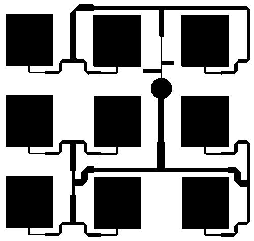
Look at the picture. The first section that we will assemble from an old iron hanger will be the 3G antenna. It is indicated in black. It does not require cleaning off the exterior paint.
- Align the wire using pliers (or your hands) and bend it 4 cm from one end at a 45 degree angle.
- Then measure 8 cm from the bend and bend the wire inward 90 degrees.
- Next, measure 9 cm again and make another bend 90 degrees inward.
- The last bend will be the same as the first - 45 degrees, here we will install a block for connecting the cables. Place the block on both ends of the cable and secure it.
The wires are connected inside the connector block. Areas 4 cm long must be cleared of braid/paint. As a result, you need to assemble two identical modules.
The next step in assembling a GSM signal amplifier is cellular communication and the Internet there will be a wireless antenna, highlighted in orange and yellow in the figure. For this section we will need a regular TV cable. First, cut off about 15-20 cm of the top covering of the cable. You will see a shielding covering, it is metallic and looks like a net. Cut it off too, but don't throw it away - it will be used as material for the red area in the picture. Just twist it and trim it if it's too long. Then install it into the connector block and secure it (the U-shape is not necessary - the connection itself is important). Then go back to the cable core, carefully cut off the insulating layer - to create a 4G directional antenna we need the bare cable.
Let's look at the drawing again. At a distance of about 5 cm from the beginning of the core, we need to make 5 turns clockwise. You can wind the cable on a screwdriver bit with a diameter of 3-6 mm. The rest of the cable core should be level. Now we need to connect our wireless antenna with the 3G antenna. To understand how to do this, look at the pictures. Remember that we need to connect the antenna core with the iron wire and secure them in the connector.
After some research, I came to the conclusion that 7 turns of cable on the outdoor antenna and 5 turns on the indoor antenna are best for 4G amplification. Use your smartphone to locate the location with the best 4G signal - place the external antenna in that location. A good signal level is determined by approximately 3 bars on the phone; an unstable signal very often jumps up and down.
If after assembling the antenna the signal remains weak, try using trial and error to find the best number of turns on the antenna for you. Usually the best signal is found on the roof of a house or close to the roof. Place the internal antenna where it is most convenient for you - in a vertical position, preferably under the ceiling, in the room in which you do business, and also at a distance from the wireless router. For ease of antenna setup, I advise you to switch your phone to 2G mode. If your home has been struck by lightning, place the antenna in a safe location. You can also try removing the case from the phone to strengthen the signal - it often jams part of the signal.
Non-insulated parts of the antenna should not touch walls or conductive surfaces.
Step 2: Addition

To boost the signal, you can try cutting a piece of kitchen foil about the length and thickness of your phone and sticking it to the left or right side of the phone (or try hiding it inside a phone case). Telephone headphones can also act as an antenna - many people have noticed that the signal is better with them.
Step 3: Extra Wire


Look at the photo above. I added an extra wire to try to increase the coverage area internal antenna. I got this result by trial and error: you need to take an additional wire 30 cm long, leave about 5 cm on one side and make 4 turns around the pencil, and then connect this wire to the connector. But this improvement will not increase the signal strength.
Step 4: Version 2.0
![]()


Show 11 more images


Version 2.0 is more like science fiction. It has more promising performance, but still needs to be installed in a place with a stable signal. If something becomes unclear, look at the photographs.
Assembly, part 1.
- Align the wire from the iron hanger.
- Make a bend at an angle of 45 degrees at a distance of 4 cm from the end of the wire, clear these 4 cm of paint/coating.
- Measure 8 cm from the bend and bend the wire inward 90 degrees.
- Measure 9 cm after this bend and make another fold 90 degrees inward.
- Next, measure 9 cm again and make another bend 90 degrees inward.
- At a distance of 8 cm, make another fold 90 degrees inward.
- Rotate the wire 90 degrees.
- Measure 9 cm from the bend and bend the wire inward 90 degrees.
- Measure 10 cm after this bend and make another bend 90 degrees inward.
- Next, measure 10 cm again and make another bend 90 degrees inward.
- Measure 11 cm from the bend.
- The last bend is the same as the first - 45 degrees inward. You also need to remove the paint/coating from it.
- Insert the ends of the wire into the connector and clamp them.
- This will be an internal and external 3G antenna combined in one.
Assembly part 2.
- Take the 3G antenna we made at the beginning of the tutorial (yellow)
- Bend the antenna wires 90 degrees.
- Attach the antenna to the connector as shown in the figure.
Assembly part 3.
- The wireless antenna has almost the same design.
- It will have 7 turns for the external module and 5 turns for the internal module.
- It should reach the antenna described in “Assembly Part 1”, so it will have to be pushed a little through the connector.
- After successful assembly, secure everything.
Step 5: Modifying the Antenna for the Wireless Router


Here's what I did with my Dlink 2750E ADSL N-300 wireless router. With a small modification to the antenna I was able to achieve a more stable connection through a solid concrete wall. You can also try this trick.
The simplest way to increase the signal level of your cell phone in a few minutes. You will need absolutely nothing other than a piece of wire of a certain length. This method will definitely help in difficult life situations.
Before finalizing the cell phone I show First level signal.
Now it is equal to: minus 99 dB - 7 units.
We disassemble the smartphone, namely, we remove back cover. SIM cards, batteries, etc. are hidden under it. We are interested in antenna connectors.

Usually, there is one connector for connecting an external GSM antenna, but sometimes there can be several of them: wi-fi, 4G, 3G. See their captions. We are interested in the GSM socket.
Making a simple antenna for a cell phone
Now you need to take a piece of insulated wire, with a central core of such a diameter that will be inserted into the central socket of this connector. The wiring must be exposed on one side for connection.
But it's not that simple: this wiring must be of a certain length in order for it to work as efficiently as possible as an external antenna.
Namely, its length should be 1/4 of the wavelength. The wavelength can be calculated from the frequency at which your cell phone operates.
Most phones operate in a range where the average frequency will be 1.9 GHz. But there are exceptions, as in my case - 0.8 GHz.
Now you need to calculate the wavelength, for this you can use numerous online services online.
So:
- For a frequency of 0.8 GHz - 38 cm, now divide by 4 and get the length of the antenna wiring - 9.5 cm.
- And for a frequency of 1.9 GHz - 16 cm, divide by 4 and get - 4 cm.

It can be bent from the top so that it does not protrude beyond the body.

Let's distribute it in the area of the battery.

We hold the antenna with our fingers; you can secure it with a piece of tape.

Close the back cover of the smartphone.

The result is visible immediately. The level increased to minus 85 dB and amounted to 14 units, which is quite good.

Well, if you find yourself in a completely hopeless situation and cannot calculate the length of the wiring, take any segment.
Bye everyone.
The GSM standard was invented by Europe in 1982, along with several related to communication via radiotelephones. The direction of the antennas was problematic; the transmitters were located near the person’s head. The harm was noticed quickly, it is widely known: employees of enterprises involved in communications receive wage increases. Without thinking twice, the standard committee introduced a new type of modulation that allows for lower power. The antennas were first made retractable, but later they took on the appearance of stumps protruding from the body of the device. The filling rapidly decreased in size along with power supplies; the direction of small-sized antennas in the gigahertz range is relatively young. The first developments concern the 50s of the last century. DIY GSM antenna: how to make it, where to install it. Let's talk in more detail.
Development of the GSM standard, GSM antennas
Those who bother to look inside a mobile phone or other gadget are powerless to see structures that resemble an antenna familiar to the eye. A thoughtful manufacturer designs, guided more by experimental considerations, devoid of a coherent theory. There is no point in thinking that a review will reveal the company's corporate secrets. Since 3G, digital standards, there has been a constant struggle to accommodate more information using fewer resources. They mentioned the harm, inside the cell phone the emitter is located in the rear wall area, separated from the user by a ground screen. Microstrip technology has been known for a long time. Veselov’s book from the 80s describes the concept in the third part.
The efficiency of a GSM cell phone antenna is low, reaching 40%. Ordinary television ones sometimes go over 90. However, people don’t care; the harm to health is minimal. Every marsh sandpiper praises a cell phone, hears the interlocutor perfectly, and when the opponent’s connection is lost, the sound disappears... This means the cell phone is bad. The radiation pattern of the GSM antenna of a cell phone is one-sided - it does not shine in the direction of the speaker - it is greatly distorted. The user changes the balance of power with his hand, let alone obstacles! A GSM antenna is made by hand to improve reception by stationary objects. Mobility is limited to use by auto repair shops.
GSM antennas of transmitting stations are well equipped and emit excellent radiation. We hear the interlocutor (if he does not make sudden movements), the opponent will lose packets while jogging or in transport. The phone receives 5 stars and transmits much worse. Incoming packets with the opponent's voice arrive regularly, outgoing packets fail.
Now readers know: it is not possible to make a GSM antenna using microstrips yourself at home. Famous companies are fighting to solve the problem. Assembly and functional design takes minimal time, production is cheap. The layout of the internals (the antenna is not easy to fit into a modest space) is much more complicated.
The following standards are in use in the Russian Federation:
- GSM 900: transmission frequency 890 – 915 MHz, reception frequency 935 – 960 MHz.
- GSM 1800: transmission frequency 1710 – 1785 MHz, reception frequency 1805 – 1880 MHz.
A microstrip antenna consists of an emitter, a dielectric substrate, and a conductive screen. As the thickness of the emitter increases, the operating range, a tenth of the wavelength, increases. The dielectric thickness is less than the specified value. We are telling this for a reason. In the Wi-Fi range, microstrips are combined into grids, sealed with a plastic case, equipped with a single screen, and act as a single command, allowing for good amplification and, therefore, to catch a more distant signal. The towers are stationary and in direct visibility. If what is said is true for a specific situation, the solution is suitable.
Here is a picture (from the website http://www.carookee.net/) of a 2.4 GHz antenna. To start working at a frequency of 1800 MHz, you need to increase the dimensions proportionally in the ratio of 4 to 3. Please note, this applies to all lines, including connecting lines. First try the functioning of one square before reducing the getinax board to the sacrifice of needs mobile communications. The scale of the portal is incorrect - see the picture with dimensions, arrows are shown. Image taken from http://www.zero13wireless.net/. The numbers are in millimeters. Proportionally remove drawing number one, determine the dimensions. The pads are square, if they are distorted, correct them graphic editor, even Paint, included by default in Windows, will do.

For other frequencies, feel free to extrapolate the drawing to all cases in proportion to the wavelength ratio. Divide 2400 MHz into the standard GSM band. The ratio 2400/1800 was taken above. By doing this, readers will choose required device GSM antennas. Containing 4x4 squares gives less gain (amplification of the GSM antenna signal), and is easier to point. The reception is blurry, it is unclear where the signal is coming from, the design is in place. In the case of a distant tower, clearly visible on the horizon, 9 squares would be appropriate. Please note that the feeder to the telephone (another receiving device) should not be long; the signal will fade on the way here, in the cable. I would like to place the device on the roof... assemble an amplifier using microstrips, buy a ready-made one in a store for the desired frequency. Find out the required number from mobile operator. Created civil service on frequencies, ask officials to talk to private owners.
Manufacturing of GSM antenna
Most readers have understood how a homemade GSM antenna can be made. The craft will require a getinax board of a suitable size with double-sided foil. Copper is applied on one side - it will be necessary to add a reflector structure from a sheet of steel or another metal with an area larger than the emitter. Then the copper is lined with the future contour of the antenna. Do it more carefully using a ruler and a corner. Then:
- The area under the antenna is covered with varnish, suitable for women's nails. The composition should not get on the surface in other places, on the joints; you can paint over large islands, then peel them off with a knife (to increase the processing speed).
- The boards are etched with copper sulfate. The foiling is double-sided - the back is completely painted over with varnish. IN otherwise the screen will not be dissolved! It’s just that the etching will not end in a conceivable time. Copper sulfate is not enough. The second side is not needed - tear it off with a knife. To preserve the screen you need to paint it with varnish.
- Etching is carried out until unnecessary areas of copper are washed off, the finished GSM antenna is washed with water, dried, and problem areas are cleaned with a knife.
- The product is placed inside a sealed plastic case of suitable dimensions on stands that do not affect the metal part. The screen needs to be grounded. Try placing it on the braid of a coaxial cable. We remind you: for WiFi, a wire with a characteristic impedance of 50 Ohms is used. How much to take for cellular communications: 50 seems appropriate because 900 MHz television is running out.
Types of GSM antennas
They wrote a lot about antennas for WiFi, readers guessed: the ranges are very similar... just take the drawings, transfer them to other frequencies, the dimensions are indicated everywhere in relation to the wavelength. Transpose sketches proportionally. The procedure is indicated above. It’s easy to find on the Internet the so-called Kharchenko antenna (biquadrat), which is a pair of frames with one common point. More advanced solutions were presented, characterized by greater amplification.
Readers will have a choice of which remote GSM antenna will be manufactured. Kharchenko's biquad design is made by radio amateurs from strips 10 mm wide, with a square side in the center of 80 mm. Dimensions were not checked, dimensions are determined by the wavelength used GSM standard. For 900, 1800 MHz the difference will be two times. Check the dimensions of the drawings carefully. The frame must be proportional to a quarter of the wavelength. The formula is known from a physics course; there is no point in presenting four drawings that differ in small details. You need to understand: an external GSM antenna is similar in structure to WiFi, we believe that any of the sections can be moved here. The difference is limited by frequency, modulation. The first does not affect reception, the second determines the size of the GSM antenna.
When using an extension cord, try to place the amplifier close to the mounting point. Wire noise greatly reduces the sensitivity of the device.
For practical manufacturing, you can take a seven-element wave channel antenna for the first time. You shouldn’t chase a “rake” of dozens of elements. Already a nine-element antenna requires instrument tuning, since, being untuned, it works worse than a seven-element one.
The Yagi antenna is named after Hidetsugo Yagi, the Japanese engineer who first published its description. The developer of the antenna was Shintaro Uda, also Japanese and a colleague of Yagi. This antenna is known to Soviet specialists and radio amateurs under the name “wave channel”. It was very widely used as a collective antenna for receiving television on all channels (with two antennas). For cellular communication bands, this antenna is especially convenient: all its dimensions are very small, and few materials are required for manufacturing. Its device is shown below.

The antenna consists of several parallel vibrators lying in the same plane. Each vibrator is made of a metal tube with a diameter of 8 mm. The figure shows a scale for precise placement of vibrators on the supporting boom. A vibrator with coordinate 0 is called a reflector. This is followed by an active half-wave vibrator. The elements following the active vibrator are called directors (directing vibrators).
The length of all vibrators and the distances between them must be maintained with great accuracy, because the purpose of the antenna is to catch maximum power without loss in conditions of a weak signal. Due to the short wavelength, the sizes of all active elements also become small. The diameter of the tubes was also not chosen by chance; the bandwidth of the antenna depends on it, and it is large enough for the given range. The antenna could be “tailored” for one specific operator: MTS, Megafon, etc., since they share frequencies among themselves, and use thinner tubes, but in this case the antenna becomes less universal.

The antenna elements can be mounted either on a metal boom or on a dielectric one. The above option was calculated for a square boom made of aluminum profile with a cross-section of 15x15 mm. If you take a non-metallic boom, for example, a pine batten, then the dimensions and distances will be the same, and perhaps the antenna will be easier to manufacture. You just need to coat the wooden part well with varnish.
The wave impedances of a half-wave vibrator and a coaxial cable are quite close to each other. But the problem is the asymmetry of the cable itself - central part and the coaxial cylinder (braid) are not the same. Therefore, it is necessary to use a balun (matching) device. It is usually made from sections of coaxial cable, but in the microwave range the cable sections become so short that it is very inconvenient to work with them. The solution may be to use microstrip lines. They can be etched onto the PCB.
The disadvantage of printed lines is the need to accurately know the dielectric constant of the board insulation at the operating frequency and very precise adherence to the width of the tracks. Fortunately, now everyone has the opportunity to create or print precise graphic documents and make a stencil out of them. Previously, this was only available at research institutes or large factories. Below is a drawing of a balun for our antenna:

Dimensions are indicated in millimeters. Board material: foil fiberglass STEF made in Russia, thickness 1.5 mm, copper thickness 50 microns. Metallization with reverse side cannot be removed, only the area located under the vibrator tubes can be etched. The tubes are attached to the board, but in such a way that they are not connected to anything. From the outside matching device vibrators (copper tubes are taken) are soldered with conductors to the tinned sections of the tracks. The cable is soldered with the central core to the outlet on the right (its length is 5–10 mm), and the cable braid is soldered to the foil on the reverse side.
A properly assembled antenna provides a gain of at least 15 dBi. By the way, let’s talk about what it is. A decibel is a logarithmic quantity, the decimal logarithm of the tenth power of a ratio of any quantity. Such units are used in acoustics and radio engineering, where they deal with huge dynamic ranges of signals.
The letter i means “isotropic” (the same in all directions, Greek). In isotropic decibels, the antenna gain is estimated relative to a simple half-wave vibrator, the gain of which is taken as unity. Every 3 decibels means a doubling of the signal strength. For example, 6 dB is already 4 times, 9 dB is 8 times. Every 6 dB, the antennas “bring the receiver and transmitter closer to each other twice” (the power flow is distributed over the area, so inverse proportionality to the square is observed here).
Attenuation in cables is also measured in decibels. For example, for the 2–3 GHz range the attenuation is -0.5 dB per linear meter of almost any cable. If our antenna is connected to the modem with a 6 m cable, then we will have to pay -3 dB of gain for this, so in reality we will get no more than 12 dB from the antenna. However, we got 4 times closer to the cell tower. If, say, the actual distance to it is 20 km, then with an antenna (electrically) it will be only 5 km. At this distance, the modem would not require any antenna other than the internal one.
For our antenna, you need to take a cable with a characteristic impedance of 75 Ohms and polyethylene semi-air insulation. Any brand of cable with these parameters. The antenna must be positioned with an arrow in the direction cell tower and place the vibrators vertically.
Mirror antenna - reflector
Another very good way to forget about how to amplify the signal is to use a reflector. The antenna of the modem itself serves as the feed. The size of the reflector is approximately 150x200 mm (great accuracy is not needed here), and the modem should be at a distance of a quarter wave from the reflector. Here you need to experiment a little, but in any case this distance is within 30–40 mm.
The reflector is made of tin, thin aluminum, even meat foil glued to cardboard, and is bent approximately in the shape of a paraboloid, so that the focus is at the point where the modem is located. Such an antenna gives a gain of about 10–12 dB (actually 9–10). By the way, this cheap homemade product, its complete analogue, well, except beautifully made, was sold in stores for 900–1000 rubles!

The disadvantage of such an antenna is the inability to place it outside - the modem and SIM card are not designed for rain and frost. The best place installations - near the window, in the direction of the cell tower. The magnitude of the signal can be assessed by the “sticks” on the signal indicator in the program for working with the modem. The quality of the connection, however, is best assessed by the speed of reception and transmission on the site speedtest.net You can try to tilt the modem with a reflector at an angle of about 45 degrees and watch the test again in order to better adapt to the polarization at the receiving location. About three or more such tests need to be done to evaluate the antenna’s ability to amplify the signal.
Lightning protection
Finally, about a very important topic. Mobile devices carried in a pocket and the issue of lightning protection for them is equivalent to lightning protection for the owner himself. A normal person would not go to a high place in a thunderstorm, either with or without a telephone. However, a normal antenna is a completely different matter. When installed outdoors, it faces a lot of risks: from a direct lightning strike to a corona discharge. In both cases, the equipment connected to such an antenna is guaranteed to be sent for repair and, in many cases, to a landfill.
 Even the harmless mirror described in the previous section, which is not connected to the modem by any wires at all, can damage it in a thunderstorm. Lightning discharges produce radio waves with a very wide spectrum of frequencies, and by chance such a spectrum can contain decent power concentrated precisely in the frequency range of the modem antenna. Microwave semiconductor elements in a modem can easily fail. Unfortunately, civilian consumer equipment is not protected from lightning in the same way that radio and electronic equipment for scientific or military purposes is protected.
ADVICE! In the event of a thunderstorm, turn off all antennas connected to your devices and remove modems exposed to reflectors. This will save you a lot of money on the purchase of new equipment and reduce the risk of data loss, which can be more expensive than any money.
The situation was hopeless. The monotonous pine forest swirled around me like a colonnade. Two hours later I again found myself in the same place where I was before. I got lost and panicked. Cell phone service didn't work. I decided to find a higher place in the hope of getting a cellular signal. He rushed into the clearing and ran out into a clearing with a lone pine tree. On the tree there is a bird feeder and a piece of paper sealed in plastic with the text: “To make a call, place the phone in the house with the buttons facing up. Turn on speakerphone or connect a headset." Next, the telephone numbers of the forestry department, the police, and the administration were listed...
When I was already bringing the mobile phone into the feeding house, I noticed that on the phone, next to the symbol indicating the antenna, the cellular signal strength diamonds flashed. The revived telephone refreshed the mind, and the house turned out to be an antenna, protected by the roof from rain and snow, and a coaxial cable running upward from it at a height of 5 meters was connected to another directional antenna. A homemade GSM signal repeater, as I didn’t immediately guess. It does not need any power supply or amplifier, which is why it is called passive. In the mobile phone itself there is no need to look for a high-frequency connector for connecting an external antenna, since its built-in antenna complements the design of the repeater antenna.
The maximum communication range at this frequency in line-of-sight conditions, when hills, houses and trees do not block the path between the antennas, reaches 35 kilometers. It’s unlikely that I could have gone that far, the thought flashed in my head, because the phone is not directly connected to the antenna, there are probably losses in the passive repeater, and I was glad to see that I was separated from civilization, no matter how 10 km.
- Found! Everyone has already been put on their feet. “The devil’s tract”, you can’t get out of there without help, there are swamps all around, a quagmire. Stay where you are, don’t go anywhere, in 1.5 hours Musya will lead me there. Musya is my horse, she knows how to get there.
I had a lot of time to study the passive repeater design.
StandardGSM 900.
The antenna must work for both reception and transmission, so its range is from 890 (880) to 960 MHz, where in the range of 890 - 915 MHz transmission from a cell phone to the base station is provided, and within 935 - 960 MHz there is signal transmission from the base station to the phone.
Here is the antenna design.
 |
| photo 1. |
DirectedGSM 900 patch antenna.
A suspended plate patch antenna is similar to a microstrip antenna. Its advantage is its small dimensions and ease of manufacture.
These are two plates and an L - vibrator. Antenna elements can be made of copper, brass, aluminum.
The larger plate is a reflector; it reflects radio waves. The braid of the coaxial cable is connected to the reflector. For the convenience of connecting the coaxial cable, desoldering and attaching the L-shaped vibrator, I used a high-frequency SMA type connector. If the cable is attached without a connector, then there is no need to drill a hole, but it is necessary to provide a dielectric fastening of the L-vibrator.
The thin plate is an active L-shaped vibrator, it is connected to the central core of the coaxial cable. I soldered it to the connector and used an additional fastening in the center using an insulator.
 |
| Rice. 2. Sketch of an L-vibrator. |
A smaller flat plate, by analogy with a “wave channel” antenna, is called a director, and is not electrically connected to anything, but is mounted on dielectric supports - racks.
 |
| Rice. 3. Director. |
Support posts can be made of plastic, foam, wood.
Purchased (factory) antennas for this frequency have a characteristic impedance of 50 Ohms, and are accordingly equipped with a cable with a characteristic impedance of 50 Ohms. So, for a homemade passive repeater, it is also advisable to adhere to a wave impedance of 50 Ohms, which is associated with lower losses compared to the 75 Ohm standard.
Options.
Compared to the gain of a quarter-wave rod, the antenna we made provided 5 dB more gain.
At the center frequency SWR = 1.2. At the edges of the range SWR = 1.5
Antenna as a passive repeater.
This antenna can be conveniently used as a stand for a mobile phone when installing a passive repeater, in which cellular telephone with its built-in antenna will be the director.
Let me remind you that the repeater consists of two antennas connected coaxial cable. One antenna is raised above the ground and aimed at base station, and the second antenna is located in close proximity to the mobile phone. At the lower table antenna, I made the director out of plastic, without changing the height of its mounting, and placed the phone on the pedestal.
When I did this experiment outside the city, the mobile phone added four levels to one risk. In addition, I received an SMS informing me that I had left home region. Typically, such messages come after 15 km from the test site, which is located on the border of two regions. In this case, the phone reliably received signals from a base station from a neighboring region.
The factory Radant 911 antenna was used as a directional antenna.
Frequency range 890 - 960 MHz, input impedance 50 Ohm, beamwidth 45 degrees, vertical polarization, gain 11 dBi. It was suspended under the roof of the gazebo, at a height of three meters from the ground. A two-meter 50 Ohm cable was connected to a patch antenna on the table. In the patch antenna, instead of the director, there was a mobile phone on a plastic pedestal.
In my experience with the repeater, I deliberately provide for additional losses by installing the antenna under the roof of the gazebo (1 cm of wood, plus soft roofing) to ensure that the passive repeater is working.