Quiet whirring of coolers
Instead of a preface While working on a computer based on the P166MMX, among other things, I found an idle power supply fan. From the words of the owner, it turned out that the fan started knocking about a year ago - which was confirmed by physical damage to the blades and the inner surface of the case, the knock stopped almost immediately - along with the life of the fan itself, the owner himself immediately forgot about it. The power reserve of a conventional 200-watt power supply was enough to ensure the performance of the system unit without leaving the operating temperature. Since then, technology has not stood still, processor frequencies have increased by an order of magnitude, the total power consumption of system units has increased, and only the nameplate power of power supplies has not increased significantly, which means that the temperature conditions of operation of key elements are quite difficult, and a malfunction of the power supply fan can lead to irreparable consequences. The impetus for the development of the device described below was the installation of a second fan in a standard power supply unit, which is blown from the system unit and the operation of both fans at a supply voltage of 9V. If the operation of a regular power supply can be checked by substituting the palm under the blown air flow, then it is quite difficult to check the operation of the second one even visually. From this came the main "technical task" - to provide visual control of the fan operation mode. Cost characteristics from the very beginning were not brought to the fore, but in the end it turned out that the cost of the finished device did not exceed the cost of the fan itself. The occupied volume of the finished device, which in addition to signaling the fan operation mode in its final form, performs a number of functions - it provides the fan motor with a reduced supply voltage with filtering of impulse noise from it and a smooth start when turned on, does not exceed the volume of a matchbox.
With minimal refinement of the circuit, the device can provide automatic speed control from temperature.
Inside the fan
The electrical circuits of all fans are approximately the same, two of their options can be found in the diagrams below from the Radio magazine: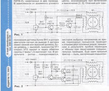
In the same article ("Repair of fans of electronic devices" by R. Aleksandrov), you can also get acquainted with the principle of their operation.
Real fan circuits can differ only in the type of elements used and the degree of their integration. For the most part, "two-wire" fans are made similarly to the first scheme. "Three-wire" fans have an additional low-power transistor in their circuit, connected according to the "open (unconnected) collector" circuit - typical circuits for switching on such fans can be found, for example, in the "datasheet" for the monitoring chip of the W83781D motherboard.
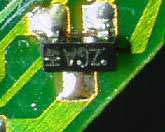
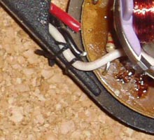
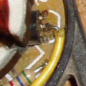
This is how the board of one of these such fans looks like (view from both sides):
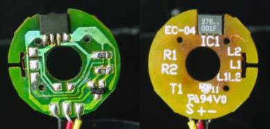
In the circuit of this fan, the Hall sensor is integrated with key transistors, the signal for the speed sensor is taken from a low-power transistor from the ZGA series.
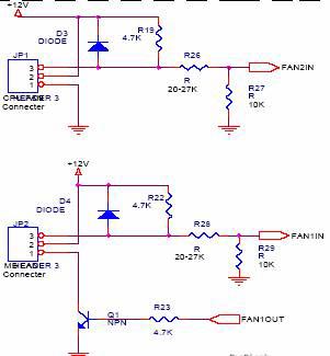
A typical switching circuit will be kept in mind when developing a fan motor rotation sensor. Here is his diagram:
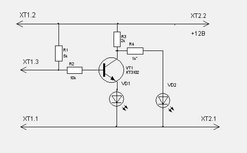
When the fan is running, both LEDs will glow, by selecting the resistance of the resistor R4 they achieve the same brightness of the glow, while when the engine is stopped, a change in the brightness of the glow should be noticeable. If the engine stops, only one of them will light up. When driving with interruptions, blinking of the LEDs will be noticeable. When connected to the gap between R2 and the base of the transistor, a capacitor with a capacitance of about 50 microfarads, when the speed changes, the brightness of the LEDs will also change. When using a few more radio elements, it is possible to provide an emergency shutdown of the system unit when the fan exits the operating mode or the use of a spare one.
As a circuit for the rotation sensor of a "two-wire" fan, one could take this one (however, this circuit was also suitable for a "three-wire" fan).
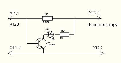
In this case, the brightness of the LED glow would inversely depend on the fan consumption current - the maximum glow in the event of a break in the fan power circuit, the absence of glow in the event of a short circuit. Setting up such a device would be reduced to selecting the resistances of two resistors - by selecting R1 (~ 5 Ohm) we set the voltage drop across it at the rated current consumption of the fan in the region of 0.5-0.75V, by selecting R2 we achieve a noticeable change in the brightness of the LED when the engine stops. The circuit has the "right to life", but we will go the other way - we will turn the "two-wire" fan into a "three-wire" one, without changing anything in its circuit. To do this is easy enough. To remove a signal whose frequency is proportional to the speed of the fan impeller, a collector of any of the key transistors is suitable. In this case, the rotation sensor can be the first circuit with the resistor R1 removed from it without changing the parameters of the remaining elements of the circuit. It remains only to remove the impeller to access the circuit elements, find the collector of one of the transistors, solder and fix the wire and reassemble. At the same time, if the fan has already been in operation, carry out routine maintenance to remove dust and lubricate the shaft.
We find the required output of the transistor by checking the continuity of the outputs relative to the positive wire of the power supply of the circuit for the presence of a low-resistance circuit with a resistance of ~ 60 Ohms and solder the wire to it.
On this, the revision of two-wire fans can be considered complete. If you do not forget how to assemble it.
Noise control
A rare user, having installed a fan in the case, does not start the fight against noise. And, as a rule, this consists in connecting the engine power between the wires + 12V and + 5V. As a rule, any arguments of opponents of such a connection are not taken into account by its supporters. I also decided to "invest my penny" in this dispute. To do this, I slightly modified the input circuits of the old Genius SM32x sound card and used it as an oscilloscope to measure ripples on both +12V and +5V power rails simultaneously using the Sony Sound Forge 7.0 audio editor.The first "oscillogram" refers to the case of connecting the fan to the +12V and 0 buses.
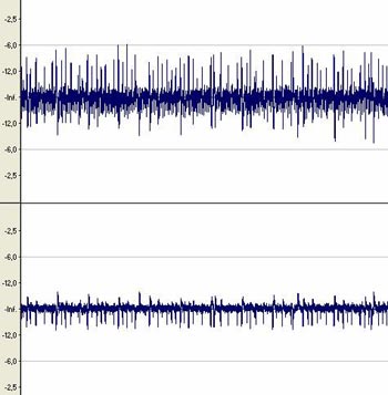
The upper waveform refers to the +12V rail, the lower waveform to the +5V rail.
And here is what the oscillogram looks like when the fan is connected to the +12V and +5V buses.
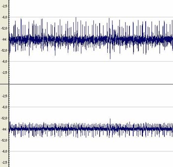
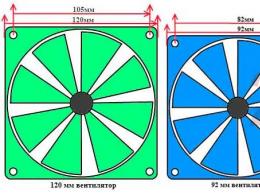
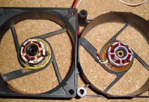
If the + 12V bus calmly endured such a connection, then pay attention to the pulses that appeared on the + 5V bus in positive values. These pulses are nothing more than switching noise of the key transistors of the motor control circuit and impulse noise of its coils. These interferences are quite strong - when measuring the peak value using an S1-55 oscilloscope, a value of more than 0.2V was obtained for the switching noise of this fan - when using a processor cooler to cool the integrated 4-channel power amplifier AF with a total power of 120W powered through an integrated stabilizer KR142EN8 background was removed only when a capacitor with a capacity of at least 1000 microfarads was connected. It is this capacitance value that is also recommended for the fan motor supply voltage reduction circuit, which will be discussed below. And now let's find out how the performance of the cooler decreases when the power is reduced. To do this, we will remove the dependences of the impeller rotation speed on the motor supply voltage for different fans (all of them are shown in the first photo), the frequency / voltage dependence for the "two-wire" fans that were under alteration was similar to the dependence for the third fan with a nominal speed of 2400 rpm. /min
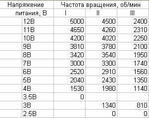
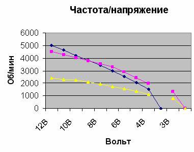
We see that the rotational speed depends linearly on the supply voltage up to the border of the working section of the supply voltage. However, the dependence of the passing air volume on the rotational speed can be taken as a quadratic one - based on this, it can be understood that the slower the engine, the less performance we will lose with the same decrease in the supply voltage compared to faster ones. With a decrease in the supply voltage, in my opinion, it is enough to stop at the border of 8-9 volts - firstly, it is here that there is a sharp decrease in acoustic noise from the rotating impeller, and, secondly, the performance drop is not so noticeable. Since, in addition to reducing acoustic noise, we are also pursuing the task of reducing impulse noise, and we have to connect a large capacitor in parallel with the supply terminals of the fan motor, we should somehow limit the initial starting current, the value of which will be the sum of the capacitor charge current and the starting current the motor itself - the measured values of the starting current for different fans gave its value not less than twice the value of the rated current. The best solution to this problem should be recognized as the use of a powerful field-effect MOSFET transistor - due to the large input resistance of the gate, you can limit yourself to small capacitors in time-setting circuits - up to 100 μF.
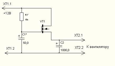
The final version was the following scheme, the setting of which is to select the capacitance C1, in which there is a smooth increase in the current consumption when turned on. Depending on the type of field effect transistor, you can get an output voltage in the range of 9.5-8.5 V. I chose the IRFZ24N (in terms of price / technical characteristics) - with it, the output voltage at an input voltage of 12V is 8.8V. This circuit can be slightly modified - the gate voltage can be supplied from the middle output of the potentiometer connected to the supply wires, by shunting one of the arms of this potentiometer with a thermistor, you can get a voltage directly or inversely proportional to the temperature change at the output. In addition, if necessary, increase the output voltage, you can shunt the drain and source terminals with a resistor with a resistance of about 50 ohms.
The final device looks like this:
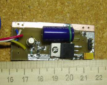
The field-effect transistor is mounted on a copper flange from a similar case soldered to the contact pad, before soldering of which, a chamfer along its contour should be chamfered. The temperature regime of the transistor under load in "one fan" with such cooling is 40 degrees. Mounting is done on a double-sided board using surface-mount radio elements (from old ISA device boards). Board fastening - in place. The LEDs are placed on the front panel.
Automatic activation of the standby fan
Consider the complete scheme of the resulting device.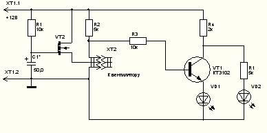
We see that if we exclude the resistor R1 from the circuit, then it is possible to open the VT2 key using the circuit that would work according to the following algorithm - there is a signal to open the key when the other fan motor stops, there is no signal - during normal operation of the fan motor. We implement this algorithm using the simplest fan sensor status detector.
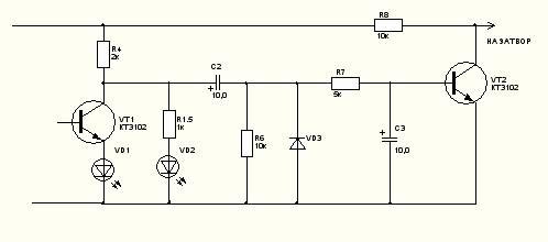
In the presence of rotation, the capacitor C2 is recharged, which causes the appearance of an alternating component on the resistor R6, the positive half-wave of which opens the transistor VT2 and recharges the capacitor C3, which prevents the transistor VT2 from closing during the negative half-wave, which through the VD3 diode "sits down" on the circuit zero. For a more accurate operation of the detector in place of this diode, it is better to use diodes with a low forward voltage, for example, germanium type D9. I used a D18 diode. In the absence of rotation, the capacitor C3 is discharged through resistors R6 and R7, as well as through the emitter junction VT2. In this case, the voltage on the VT2 collector rises, which leads to the opening of the field-effect transistor and the supply voltage to the backup fan.
By selecting the capacitance of the capacitor C3, it is possible to "test" the operation of the backup fan at the first start during the charging time of this capacitor.
When the main fan is replaced with a serviceable backup fan, it stops again.
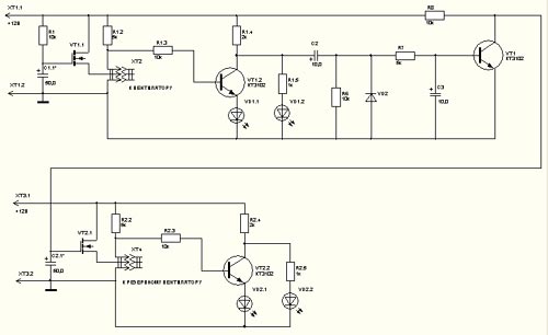
Here is a complete diagram of such a device:
And here is its appearance in the assembled state:
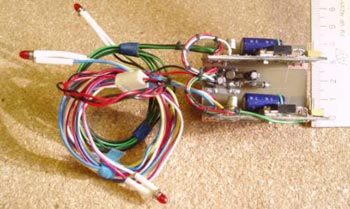
Two fan sensor boards are installed on the cross-board, on which the detector is located. Fans are connected to standard three-prong fan plugs. Power can be supplied, for example, through a standard fan connector (as in the picture). Instead of pairs of LEDs, two-anode two-color LEDs can be used.
Literature on the topic
- Magazine "Radio" №12, 2001 "Repair of fans of electronic devices", R. Aleksandrov, pp. 33-35.
- Magazine "Radio" №2, 2002 "Audible fan failure alarm", D. Frolov, p.34