Color music for 12 volts. Making color music from LED strip
Additionally
-
IN: I bought a tape with contacts G, R, B, 12 on it. How to connect?
A: This is the wrong tape, you can throw it awayIN: The firmware loads, but the error “Pragma message...” appears in red letters.
A: This is not an error, but information about the library versionIN: What should I do to connect a ribbon of my own length?
A: Count the number of LEDs, before loading the firmware, change the very first setting in the sketch, NUM_LEDS (the default is 120, replace it with your own). Yes, just replace it and that’s it!!!IN: How many LEDs does the system support?
A: Version 1.1: maximum 450 pieces, version 2.0: 350 piecesIN: How to increase this number?
A: There are two options: optimize the code, take another library for the tape (but you will have to rewrite some of it). Or take Arduino MEGA, it has more memory.IN: Which capacitor should I use to power the tape?
A: Electrolytic. The voltage is 6.3 Volts minimum (more is possible, but the conductor itself will be larger). Capacitance - at least 1000 uF, and the more the better.IN: How to check the tape without Arduino? Does the tape burn without Arduino?
A: The address strip is controlled using a special protocol and works ONLY when connected to a driver (microcontroller) -
YOU CAN ASSEMBLE THE CIRCUIT WITHOUT A POTENTIOMETER! To do this, use the POTENT parameter (in the sketch in the settings block in the settings signal) assign 0. The internal reference voltage reference source of 1.1 Volt will be used. But it will not work at any volume! For the system to work correctly, you will need to select the volume of the incoming audio signal so that everything is beautiful, using the previous two setup steps.
-
Version 2.0 and higher can be used WITHOUT an IR REMOTE, modes are switched with a button, everything else is configured manually before loading the firmware.
-
How to set up another remote control?
Other remote controls have different button codes, use the sketch to determine the button code IR_test(versions 2.0-2.4) or IRtest_2.0(for versions 2.5+), available in the project archive. The sketch sends the codes of the pressed buttons to the port monitor. Next in the main sketch in the section for developers There is a definition block for the remote control buttons, just change the codes to your own. You can calibrate the remote control, but honestly it’s too lazy. -
How to make two volume columns by channel?
To do this, it is not at all necessary to rewrite the firmware; it is enough to cut a long piece of tape into two short ones and restore the broken electrical connections with three wires (GND, 5V, DO-DI). The tape will continue to work as one piece, but now you have two pieces. Of course, the audio plug must be connected with three wires, and the mono mode is disabled in the settings (MONO 0), and the number of LEDs must be equal to the total number on the two segments.
P.S. Look at the first diagram in the diagrams! -
How to reset settings that are stored in memory?
If you've played around with the settings and something goes wrong, you can reset the settings to factory settings. Starting from version 2.4 there is a setting RESET_SETTINGS, set it to 1, flash it, set it to 0 and flash it again. The settings from the sketch will be written to memory. If you are on 2.3, then feel free to update to 2.4, the only difference is the versions new setting, which will not affect the operation of the system in any way. In version 2.9 there was a setting SETTINGS_LOG, which outputs the values of settings stored in memory to the port. So, for debugging and understanding.
To assemble LED color music with your own hands, you need to have basic knowledge of electronics, be able to read schematics and work with a soldering iron. In the article we will look at how LED color music works, the basic working diagrams on the basis of which you can assemble ready-made devices yourself, and at the end we will step-by-step assemble the finished device using an example.
Color music installations are based on the method of frequency conversion of music and its transmission, through separate channels, to control light sources. As a result, it turns out that depending on the basic musical parameters, the operation of the color system will correspond to it. This trailer is the basis for the scheme for assembling color music on LEDs with your own hands.
Typically, at least three different colors are used to create color effects. It can be blue, green and red. Mixed in different combinations, with different durations, they can create an amazing atmosphere of fun.
LC and RC filters are capable of separating the signal into low, medium and high purity; they are the ones that are installed and configured in a color music system using LEDs.
Filter settings are set to the following parameters:
- up to 300 Hz at low pass filter As a rule, its color is red;
- 250-2500 Hz for medium, color green;
- everything above 2000 Hz converts into a high-pass filter, as a rule, the operation of the blue LED depends on it.
The division into frequencies is carried out with slight overlap, this is necessary to obtain different color shades during operation of the device.
The choice of color in this color music scheme is not important, and if you wish, you can use LEDs of different colors at your discretion, change places and experiment; no one can prohibit it. Various frequency fluctuations combined with the use of a non-standard color scheme can significantly affect the quality of the result.
Such circuit parameters as the number of channels and their frequency are also available for adjustment, from which we can conclude that color music can use a large number of LEDs of different colors, and each of them can be individually adjusted in frequency and channel width.
What is needed to make color music
Resistors for color music installations, produced in-house, can only be used constant, with a power of 0.25-0.125. Suitable resistors can be seen in the figure below. The stripes on the body indicate the resistance value.

The circuit also uses R3 resistors, and trimmers R - 10, 14, 7 and R 18, regardless of type. The main requirement is the ability to install on the board used during assembly. First option LED color music, assembled using a resistor variable type with the designation SPZ-4VM and imported - tuning.

As for capacitors, you need to use parts with an operating voltage of 16 volts, no less. Can be any type. If you have difficulty finding capacitor C7, you can connect two smaller capacitors in parallel to obtain the required parameters.
The capacitors C1, C6 used in the LED color music circuit must be capable of operating at 10 volts, respectively C9–16V, C8–25V. If, instead of old Soviet capacitors, you plan to use new, imported ones, then it is worth remembering that they have a difference in designation; you need to determine in advance the polarity of the capacitors that will be installed, otherwise you can confuse and damage the circuit.

To make color music, you will also need a diode bridge with a voltage of 50V and an operating current of about 200 milliamps. In cases where it is not possible to install a ready-made diode bridge, you can make it from several rectifier diodes; for convenience, they can be removed from the board and mounted separately using a smaller board.

The parameters of the diodes are selected similarly to the diodes used in the factory version of the bridge.
LEDs should be red, blue and green. For one channel you will need six of them.
Another necessary element is a voltage stabilizer. A five-volt stabilizer is used, imported, with article number 7805. You can also use 7809 (nine-volt), but then you need to exclude resistor R22 from the circuit, and instead put a jumper connecting the negative bus and the middle terminal.
Connect color music with music center, you can use a three-pin jack connector.

And the last thing you need to have for assembly is a transformer with suitable voltage parameters.
General diagram for assembling color music, which uses the parts described in the photo below.

Several working schemes
Below we will propose several working schemes for LED color music.
Option #1
Any type of LED can be used for this circuit. The main thing is that they are super bright and different in glow. The circuit works on the following principle: the signal from the source is transmitted to the input, where the channel signals are summed and then sent to a variable resistance. (R6, R7, R8) Using this resistance, the signal level for each channel is adjusted, and then sent to the filters. The difference between filters is in the capacity of the capacitors used to assemble them. Their purpose, as in other devices, is to transform and purify the sound range within certain boundaries. These are high, mid and low frequencies. For adjustment, adjustment resistors are installed in the color music circuit. Having gone through all this, the signal goes to a microcircuit that allows you to install various LEDs.

Option No. 2
The second version of LED color music is distinguished by its simplicity and is suitable for beginners. The circuit involves an amplifier and three channels for frequency processing. A transformer is installed, which can be dispensed with if the input signal is sufficient to open the LEDs. As in similar circuits, adjustment resistors are used, designated as R4 - 6. Any transistors can be used, the main thing is that they transmit more than 50% of the current. Essentially, nothing more is required. The circuit can be improved, if desired, to obtain a more powerful color and music installation.

Step-by-step assembly of the simplest color music model
To assemble a simple LED color music you will need the following materials:
- LEDs measuring five millimeters;
- wire from old headphones;
- original or analogue of transistor KT817;
- 12 volt power supply;
- several wires;
- a piece of plexiglass;
- glue gun
The first thing you need to start with is to make the body of the future color music from plexiglass. To do this, it is cut to size and glued together with a glue gun. It is better to make the box rectangular. The sizes can be adjusted to suit you.

To calculate the number of LEDs, divide the adapter voltage (12V) by working LEDs(3B). It turns out we need to install 4 LEDs in the box.
We strip the cable from the headphones, there are three wires in it, we will use one for the left or right channel, and one for the common one.

We don't need one wire and it can be insulated.
The diagram of a simple LED color music looks like this:

Before assembly, we lay the cable inside the box.
LEDs have polarity, so when connecting, it must be taken into account.
During the assembly process, you should try not to heat the transistor, as this can lead to its breakdown, and pay attention to the markings on the legs. The emitter is designated as (E), base and collector, respectively (B) and (K). After assembly and inspection, you can install the top cover.

Ready-made version of LED color music
In conclusion, I would like to say that assembling color music using LEDs is not as difficult as it might seem at first. Of course, if you need a device with a beautiful design, then you will have to spend a lot of time and effort. But to make simple color music for informational or entertainment purposes, it is enough to assemble one of the diagrams presented in the article.
simple scheme of color music using 220V lamps
Everyone knows and almost everyone assembles this device that flickers and blinks to the music - color music. On the Internet, many search for color music schemes using various queries and they are different everywhere. I present to your attention the diagram below appearance which you see in the pictures. And so, circuit of working color music for 220 Volts on teristors
A simple color scheme
 It will require the bare minimum of parts.
We buy colored incandescent lamps 220V
Considering that the output stage of the color music is made of thyristors, it has high power. If thyristors are placed on heat sinks, then each channel can be loaded with 1000 watts. But for a home, 60-100 watt lamps are quite enough.

Drawing of a printed circuit board for light and music

I did not use laser-iron technology for such a simple board design. I simply printed the image as a mirror image and placed it on the foil.

To prevent the paper from moving, we secure it with tape or something else and mark the places of future holes

We paint the tracks themselves with nitro paint

Any transformer from a Chinese power supply, whether from a radiotelephone or something else, will be suitable as a transformer.
And look at the completely soldered board

We attach the cartridges to the aluminum corner

In addition to the photo sent
In this article we will talk about color music. Probably every beginning radio amateur, and not only others, at one time or another had the desire to assemble color music. What this is, I think, is known to everyone - to put it simply, this is a creation visual effects, changing to the beat of the music.
That part of color music that emits light can be performed on powerful lamps, for example, in a concert setup, if color music is needed for home discos, it can be done using ordinary 220 volt incandescent lamps, and if color music is planned, for example, as computer modding, for everyday use, it can be done on LEDs.

Recently, with the advent of LED strips on sale, color and music consoles using such LED strips are increasingly used. In any case, to assemble Color Musical Installations (CMUs for short) a signal source is required, which can be a microphone with several amplifier stages assembled.

The signal can also be taken from line output devices, sound card computer, from the output of an mp3 player, etc., in this case you will also need an amplifier, for example two stages on transistors, I used KT3102 transistors for this purpose. The preamplifier circuit is shown in the following figure:

Preamplifier - circuit
The following is a diagram of a single-channel color music with a filter, working in conjunction with a preamplifier (above). In this circuit, the LED flashes along with the bass (low frequencies). To match the signal level, a variable resistor R6 is provided in the color music circuit.

There are more simple circuits color music, which any beginner can assemble, on 1 transistor, and also not requiring a preamplifier, one of such circuits is shown in the picture below:

Color music on a transistor
The pinout diagram for the Jack 3.5 plug is shown in the following figure:

If for some reason it is not possible to assemble a pre-amplifier using transistors, you can replace it with a transformer turned on as a step-up. Such a transformer must produce voltage on the windings of 220/5 Volts. The transformer winding with a smaller number of turns is connected to a sound source, for example, a radio tape recorder, parallel to the speaker, and the amplifier must produce a power of at least 3-5 watts. Winding with big amount turns is connected to the color music input.
![]()
Of course, color music is not only single-channel, it can be 3, 5 or more multi-channel, when each LED or incandescent lamp blinks while reproducing the frequencies of its range. In this case, the frequency range is set by using filters. In the following circuit, a three-channel color music system (which I recently assembled myself), there are capacitors as filters:

If we wanted to use not individual LEDs in the last circuit, but an LED strip, then the current-limiting resistors R1, R2, R3 should be removed from the circuit. If the strip or LED is used RGB, it must be made with a common anode. If you plan to connect long LED strips, then to control the strip you should use powerful transistors installed on radiators.

Since LED strips are designed for 12 Volt power supply, we should accordingly raise the power supply in the circuit to 12 Volts, and the power supply should be stabilized.
Thyristors in color music
Until now, the article has only talked about color and music devices using LEDs. If there is a need to assemble a digital control unit using incandescent lamps, then thyristors will need to be used to control the brightness of the lamps. What is a thyristor anyway? This is a three-electrode semiconductor device, which accordingly has Anode, Cathode And Control electrode.

KU202 Thyristor
The figure above shows the Soviet thyristor KU202. Thyristors, if you plan to use them with a powerful load, also need to be mounted on a heat sink (radiator). As we see in the figure, the thyristor has a thread with a nut and is attached similarly to powerful diodes. Modern imported ones are simply equipped with a flange with a hole.

One of these thyristor circuits is shown above. This is a three-channel color music circuit with a step-up transformer at the input. When selecting analogue thyristors, you should look at the maximum permissible voltage of the thyristors, in our case for the KU202N it is 400 volts.

The figure shows a similar color music circuit to the one shown above, the main difference in the lower circuit is that there is no diode bridge. Also, LED color music can be built into system unit. I assembled such a three-channel color music with a preamplifier in a casing from a cider. In this case, the signal was taken from the computer sound card using a signal divider, the outputs of which were connected active acoustics and color music. It is possible to adjust the signal level, both overall and separately by channel. The preamplifier and color music were powered from a 12 Volt Molex connector (yellow and black wires). The preamplifier and three-channel color music circuits for which they were assembled are shown above. There are other LED color music schemes, for example this one, also three-channel:

Color music on 3 LEDs - diagram
In this circuit, unlike the one I assembled, inductance is used in the mid-frequency channel. For those who want to first assemble something simpler, here is the following diagram for 2 channels:

If you collect color music using lamps, you will have to use light filters, which in turn can be either homemade or purchased. The figure below shows the filters that are commercially available:

Some fans of color and musical effects assemble devices based on microcontrollers. Below is a diagram of four-channel color music on the AVR tiny 15 MK:

The Tiny 15 microcontroller in this circuit can be replaced with tiny 13V, tiny 25V. And at the end of the review, I would like to say on my own that color music using lamps is inferior in terms of entertainment to color music using LEDs, since lamps are more inertial than LEDs. And for self-repetition, I can recommend this one:
Almost every novice radio amateur, and not only others, had a desire assemble a color music console or running fire to add variety to your music listening experience in the evening or on holidays. In this article we will talk about a simple color music console assembled on LEDs, which even a novice radio amateur can assemble.
1. The operating principle of color music consoles.
Operation of color music consoles ( CMP, CMU or SDU) is based on frequency division of the spectrum sound signal with its subsequent transmission via separate channels low, average And high frequencies, where each channel controls its own light source, the brightness of which is determined by the vibrations of the sound signal. The end result of the console's operation is to obtain a color scheme that matches the piece of music being played.
To obtain the full range of colors and maximum quantity color shades in color music consoles use at least three colors:

The frequency spectrum of the audio signal is divided using LC- And RC filters, where each filter is tuned to its own relatively narrow frequency band and passes through only vibrations of this part of the audio range:
1
. Low pass filter(low-pass filter) transmits vibrations with a frequency of up to 300 Hz and the color of its light source is chosen red;
2
. Mid Pass Filter(PSC) transmits 250 – 2500 Hz and the color of its light source is chosen green or yellow;
3
. Filter higher frequencies
(HPF) transmits from 2500 Hz and above, and the color of its light source is chosen blue.

There are no fundamental rules for choosing the bandwidth or color of the lamps, so each radio amateur can use colors based on the characteristics of his perception of color, and also change the number of channels and frequency bandwidth at his own discretion.
2. Schematic diagram of a color music console.
The figure below shows a diagram of a simple four-channel color and music set-top box assembled using LEDs. The set-top box consists of an input signal amplifier, four channels and a power supply that supplies the set-top box with AC power.

Signal audio frequency supplied to contacts PC, OK And General connector X1, and through resistors R1 And R2 goes to the variable resistor R3, which is a regulator of the input signal level. From the middle terminal of the variable resistor R3 sound signal through a capacitor C1 and resistor R4 enters the input preamp, assembled on transistors VT1 And VT2. The use of an amplifier made it possible to use the set-top box with almost any audio source.
From the output of the amplifier, the audio signal is supplied to the upper terminals of trimming resistors R7,R10, R14, R18, which are the load of the amplifier and perform the function of adjusting (tuning) the input signal separately for each channel, and also set the desired brightness of the channel LEDs. From the middle terminals of the trimming resistors, the audio signal is supplied to the inputs of four channels, each of which operates in its own audio range. Schematically, all channels are designed identically and differ only in RC filters.
Per channel higher R7.
The channel bandpass filter is formed by a capacitor C2 and passes only the high-frequency spectrum of the audio signal. Low and medium frequencies do not pass through the filter, since the capacitor resistance for these frequencies is high.
Passing the capacitor, the high-frequency signal is detected by a diode VD1 and is fed to the base of the transistor VT3. The negative voltage appearing at the base of the transistor opens it, and a group of blue LEDs HL1 — HL6 included in its collector circuit are ignited. And the greater the amplitude of the input signal, the stronger the transistor opens, the brighter the LEDs burn. To limit the maximum current through the LEDs, resistors are connected in series with them R8 And R9. If these resistors are missing, the LEDs may fail.
Per channel average frequency signal is supplied from the middle terminal of the resistor R10.
The channel bandpass filter is formed by a circuit С3R11С4, which for low and higher frequencies has significant resistance, therefore, to the base of the transistor VT4 Only mid-frequency oscillations are received. LEDs are included in the collector circuit of the transistor HL7 – HL12 Green colour.
Per channel low frequency signal is supplied from the middle terminal of the resistor R18.
The channel filter is formed by a circuit С6R19С7, which attenuates signals of medium and high frequencies and therefore to the base of the transistor VT6 Only low frequency vibrations are received. The channel load is LEDs HL19 – HL24 Red.
For a variety of colors, a channel has been added to the color music console yellow colors. The channel filter is formed by a circuit R15C5 and operates in a frequency range closer to low frequencies. Input signal comes to the filter from a resistor R14.
Powered color music console constant voltage 9V. The power supply unit of the set-top box consists of a transformer T1, diode bridge made on diodes VD5 – VD8, microcircuit voltage stabilizer DA1 type KREN5, resistor R22 and two oxide capacitors C8 And C9.
The alternating voltage rectified by the diode bridge is smoothed by an oxide capacitor C8 and goes to the voltage stabilizer KREN5. From the output 3 microcircuit, a stabilized voltage of 9V is supplied to the set-top box circuit.
To obtain an output voltage of 9V between the negative bus of the power supply and the output 2 chip included resistor R22. By changing the resistance value of this resistor, the desired output voltage is achieved at the pin 3 microcircuits.
3. Details.
The set-top box can use any fixed resistors with a power of 0.25 - 0.125 W. The figure below shows resistor values that use colored stripes to indicate the resistance value:

Variable resistor R3 and tuning resistors R7, R10, R14, R18 of any type, as long as they fit the size of the printed circuit board. In the author's version of the design, a domestic variable resistor of the SP3-4VM type and imported trimming resistors were used.

Permanent capacitors can be of any type, and are designed for an operating voltage of at least 16 V. If difficulties arise in purchasing a C7 capacitor with a capacity of 0.3 μF, it can be composed of two connected in parallel with a capacity of 0.22 μF and 0.1 μF.
Oxide capacitors C1 and C6 must have an operating voltage of at least 10 V, capacitor C9 not below 16 V, and capacitor C8 not below 25 V.

Oxide capacitors C1, C6, C8 and C9 have polarity, therefore, when mounting on a breadboard or printed circuit board this must be taken into account: for Soviet-made capacitors, the positive terminal is indicated on the case; for modern domestic and imported capacitors, the negative terminal is indicated.

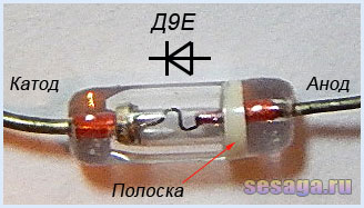
Diodes VD1 – VD4 any from the D9 series. A colored stripe is applied to the diode body on the anode side, identifying the letter of the diode.
As a rectifier assembled on diodes VD5 - VD8, a ready-made miniature diode bridge is used, designed for a voltage of 50V and a current of at least 200 mA.

If you use rectifier diodes instead of a ready-made bridge, you will have to slightly adjust the printed circuit board, or even move the diode bridge outside the main board of the set-top box and assemble it on a separate small board.
For self-assembly Bridge diodes are taken with the same parameters as the factory bridge. Any rectifier diodes from the KD105, KD106, KD208, KD209, KD221, D229, KD204, KD205, 1N4001 - 1N4007 series are also suitable. If you use diodes from the KD209 or 1N4001 - 1N4007 series, then the bridge can be assembled directly from the printed circuit board directly on the contact pads of the board.
LEDs are standard with yellow, red, blue and green colors. Each channel uses 6 pieces:

Transistors VT1 and VT2 from the KT361 series with any letter index.

Transistors VT3, VT4, VT5, VT6 from the KT502 series with any letter index.

Voltage stabilizer type KREN5A with any letter index (imported analogue 7805). If you use nine-volt KREN8A or KREN8G (imported analogue 7809), then resistor R22 is not installed. Instead of a resistor, a jumper is installed on the board, which will connect the middle pin of the microcircuit to the negative bus, or this resistor is not provided at all during the manufacture of the board.

To connect the set-top box to the sound source, a three-pin jack connector is used. The cable is taken from a computer mouse.

Power transformer - ready-made or home-made with a power of at least 5 W with a voltage on the secondary winding of 12 - 15 V with a load current of 200 mA.
In addition to the article, watch the first part of the video, which shows First stage color music console assembly
This ends the first part.
If you are tempted make color music using LEDs, then select the parts and be sure to check the serviceability of diodes and transistors, for example. And we will carry out the final assembly and configuration of the color and music console.
Good luck!
Literature:
1. I. Andrianov “Attacks for radio receivers.”
2. Radio 1990 No. 8, B. Sergeev “Simple color and music consoles.”
3. Operating manual for the “Start” radio designer.