Connection interfaces - varieties and applications. External wired interfaces What does it mean that the wired interface is not available
Approximately three million users, perfect picture quality and accessibility are just some of the advantages of IPTV television, a service offered by Rostelecom. Meanwhile, technical support specialists often have to answer the question: why does interactive television not work at Rostelecom, despite the fact that there are no problems with the Internet connection. Despite the fact that RTK specialists are constantly improving the quality of the service, problems with IPTV happen, and this is far from uncommon. If you have a situation similar to the one when Rostelecom television does not work, but the Internet works, you should not fall into despair, since in most cases the problem is solved, even without the intervention of specialists.
Whatever the quality of the services provided, any technique can fail and, unfortunately, the perpetual motion machine has not yet been invented. I would like to warn you in advance: if your Rostelecom TV freezes, 50% of it can be fixed by rebooting the receiver. Fascinated by the variety of media content from IPTV, many users of IPTV set-top boxes do not turn them off from the power source for months, only putting them into Stand-BY mode before going to bed. Considering that the service is constantly being improved, and versions with new firmware appear, your equipment simply needs to be updated. In this case, disconnecting the router and set-top box from the network can help.
Among the possible problems, one can also highlight the connection of the TV tuner to the “wrong” LAN socket. Usually, the manufacturer allocates certain LAN ports to connect a set-top box, and if you decide to connect it through another port intended for Internet connection, for example, nothing will happen. If you did everything right, but Rostelecom does not show television, you should look for the reason in another direction.
Important! If you are using ADSL, you must use the LAN-4 port to connect, the same port is assigned when connecting via fiber optic. In the case of using two or three set-top boxes, the LAN-3 and LAN-2 ports are used, but never the LAN-1 port intended for connecting to the Internet.
You may encounter the fact that an inscription is displayed on the TV saying that there is no signal from the set-top box. This happens quite often, and users ask why the television from Rostelecom does not work when the Internet is working, if everything is done correctly and the receiver is connected according to the rules. In most cases, this happens because you did not indicate to the device the input through which the set-top box is connected, and modern television receivers provide several outputs for connection.
Error no IP address
Among the most common reasons for the lack of a signal, if Rostelecom shows a black screen, you should look for the reason in the Wi-Fi router settings, although this can happen due to incorrect port settings by the provider. First of all, you must reboot the router and set-top box, and if you did this, and the TV does not work, you can check the quality of the twisted-pair connection - the cable leading to the set-top box. If the connections are tight, you should try to connect using another cable - the problem may not be that there is no signal, but that the cable is simply worn out. Changes in the router settings can fix the set-top box malfunction error from Rostelecom, and this can be done at http://192.168.1.1, or by contacting support.
Endless running rabbit
The first inclusion of some models of IPTV set-top boxes is very popular with children, as a rabbit appears on the screen, and then a cartoon “about hares” is shown. In fact, this is a problem associated with not receiving firmware from Rostelecom via multicast. There can be two reasons for this:
- An error occurred when configuring the router, and in this case, the set-top box may be assigned the wrong IP address. Setting the port to STB can help in this case, and don't forget to make sure IGMP Snooping has been enabled.
- Problems related to a hardware configuration error on the part of the service provider. This rarely happens, and only technical service personnel can deal with the problem.
Important! If you think that the set-top box has stopped working due to a problem related to a router connection error (the port for STB connection is not configured), change the LAN port to the WLAN port in parallel.
Invalid login and password
 A lot of trouble is caused by problems related to authorization on the IPTV server or on the authorization server. You can enter, for example, an incorrect username or password. If you are sure that you entered everything correctly, and Rostelecom interactive TV does not work, you should refer to the settings of the router or modem. In particular, checking the configuration settings of the router and rebooting the receiver itself can help. If IPTV from Rostelecom does not work, you should still contact technical support, whose specialists will check the data for authorization.
No signal
If, after connecting the set-top box, there is no signal on the TV, as evidenced by the absence of an image and sound, you may need to set up the TV receiver itself. The fact is that various devices can be connected to modern TVs, so it is very important that the connection port matches the settings, since not all TV receivers have learned to do this in automatic mode. First, you need to find the Source button on the remote control, which is responsible for the signal source. By clicking on this button, you will be taken to a menu in which you need to select the desired connection port. If you do everything right, a good quality image and a signal from Rostelecom will appear immediately. The problem may also be a loose fit of the contacts, and to fix it, it is enough to disconnect the cable and reconnect it. If you can’t solve the problem on your own, you won’t be able to do without the help of a specialist.
loading error
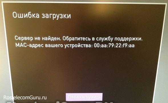 Quite often, when users say that the Rostelecom TV set-top box is not working, they mean the inscription “Server not found” that appears on the screen. Below this inscription, users are advised to contact customer support. In fact, if the server is unavailable and Rostelecom does not show channels due to a server failure, you will not be able to solve the problem on your own. Help can only be provided by specialists who will have to turn to help.
Users of IPTV television can see on a black screen an inscription warning about a problem connecting to the server, while the system reports that the network interface is connected, and the IP address has been received. This means that the Rostelecom server is unavailable due to a failure on the provider's networks - a fairly common phenomenon. In this case, leave the set-top box enabled and wait until the problem is resolved on the server. If the work of the set-top box is not restored, it must be rebooted. First, the set-top box itself turns off, then the router, after turning on the router, 5-7 minutes should pass, after which you can turn on the receiver. The problem must be solved.
Image with squares
If the image comes with freezes, or it is impossible to watch Rostelecom television due to the appearance of a blurry picture with “squares”, while the sound does not disappear, but “stutters”, you must restart the set-top box again. If this measure did not help, or helped for a while, you can try disconnecting all devices from the router, with the exception of the TV tuner itself, try also turning off Wi-Fi. Turning on all devices gradually, you will determine the source of the channel download, and most often this happens on ADSL lines, and especially in cases where the channel is busy with downloads from file hosting.
Wired interface not available
If you see a message about the absence of a wired interface, remember that the problem is a malfunction of your Internet line. Most likely, it can help solve it standard procedure reboot the router and receiver. You should also not forget about possible mechanical damage to the cable. You can check why the network interface is not connected by connecting a new cable.
Service (login) blocked
If Rostelecom channels are not shown, this may also mean that the service (login) is blocked. Timely payment for interactive television services can solve the problem, and you can check the status of your account in your personal account on the Rostelecom website, in some cases replacing the set-top box helps.
The router is the main component of the local network and performs most of the basic functions when exchanging data. Not only the capabilities of your home network, but also its performance and stability will depend on it. Therefore, his choice should be taken very seriously.
Introduction
In the first article in the article series, we found out that the router is the main component of the local network and performs most of the basic functions when exchanging data. And if so, then his choice should be taken very seriously. It is on it that many of the capabilities of your home network, its performance and stability will depend.
To make it easier for you to choose this complex device, let's look at the main characteristics of routers and see what they are responsible for. I will deliberately simplify some of the wording when describing certain functions, trying not to overload inexperienced users with complex technical information.
Router types
In general, routers can be divided into two large groups - wired and wireless. Already by the names it is clear that all devices are connected to the first ones only with the help of cables, and to the second ones, both with the help of wires and without them, using radio WiFi technologies. Therefore, at home, it is wireless routers that are most often used, which allow providing the Internet and networking computer equipment using various communication technologies.
Conclusion 1: If you are not pursuing any specialized tasks, then it is better to buy a wireless router. This universal solution will allow you to network equipment using various data transmission technologies.
Wired connection interfaces
To connect computers and other devices using wires, routers have special T-shaped sockets called ports. In models oriented to home use, their number is usually five - four LAN sockets (output interface) and one WAN or DSL (input interface).

The devices that you want to network are connected to the LAN ports, and the cable of the provider that provides broadband (high-speed) Internet access through a dedicated channel is connected to the WAN port. By the way, that's why for many routers the WAN port is signed with the word INTERNET.

Unfortunately, in some regions, broadband network access is still not available or very expensive. In this case, the Internet connection can be made using a telephone line (DSL or ADSL). Then, the built-in DSL modem acts as an external (input) network interface in the router, and instead of the WAN jack, there is a connector for a telephone cable marked DSL or ADSL at the back.

Recently, the wireless method of connecting to the Internet using 3G and LTE (4G) mobile technologies, capable of providing high data exchange speeds, is gaining more and more popularity. This is especially true for large cities with a good coverage area of cellular networks.
If you plan just such a way to connect to the global web, then you need to choose a router with support for 3G / 4G USB modems or with an already built-in mobile modem. In the first version, the router is equipped with a USB port for connecting modems and built-in software support for their main models, a complete list of which can usually be found in the user manual.

In the second case, where the modem is already built in, there is a slot for installing a SIM card from any operator. This option is universal, but not the only one offered on the market.
.jpg)
Often, routers with built-in 3G / LTE modems are offered by the providers themselves (operators cellular networks) as proprietary solutions. In this case, a separate purchase and installation of a SIM card is not required, since the device is already configured to work in a specific cellular network.
Conclusion 2: Before buying a router, you first need to decide on the company that will provide you with access to the Internet (provider) and find out what method of connecting to the global network they use.
Modern routers use two types of LAN technologies. The first, Fast Ethernet, allows devices to communicate on the network at speeds up to 100 Mbps. The second, Gigabit Ethernet - up to 1000 Mbps. If you plan to actively exchange large files between computers on your home network, such as high-quality video, then choose a router with gigabit LAN ports (10/100/1000BASE-TX). If the main task is simply to provide Internet to all devices on the home network, then you can limit yourself to a budget solution with a 100-megabit output interface (10/100BASE-TX). Indeed, today in many regions of Russia the bandwidth of Internet channels of private users does not exceed 10 Mbps, and only in large cities the speed of access to the World Wide Web can reach 100 Mbps.
Conclusion 3: In most cases, to provide Internet to all devices participating in the local network, a router with a speed of LAN ports 10/100 Mbps c. But for the active exchange of bulk data between computers on a home network, a router with the maximum speed of information transfer through LAN equal to 1 Gbps. But it will cost more.
Another important characteristic of the router that you should pay attention to is the throughput of the WAN interface. This applies to those who plan to connect to the Internet using broadband access, which can provide high speed information exchange. It is important to know that WAN capabilities in many budget router models (up to 2000 rubles) are limited to data transfer rates of 30 - 35 Mbps. This means that by purchasing such a router and connecting to the Internet, for example, at a speed of 60 Mbps, you will be able to use the channel’s capabilities only by half, and you will overpay money in vain.
Unfortunately, for some reason, manufacturers do not consider it necessary to inform users of the throughput values of WAN ports in the official technical specifications of devices. Therefore, these numbers are not usually published in any of the descriptions of routers, including those provided by many computer stores. The only way out of this situation is to use the search for the necessary information on the Internet. Fortunately, finding it in most cases is not difficult.
Conclusion 4: Before buying a router, decide at what speed you plan to connect to the Internet. If the channel is wide (over 30 Mbit/ c), then be sure to find out the throughput WAN port of the selected model of your future router.
If in your area you can only connect to the World Wide Web through a telephone line, then you should not worry about the bandwidth of the incoming network interface. Almost all modern routers have support for the most advanced on this moment ADSL 2+ standard, which provides a maximum incoming stream speed of 24 Mbps, and outgoing - 3.5 Mbps.
Wireless connection interfaces
As already mentioned, wireless routers contain a Wi-Fi module responsible for transmitting data using a radio signal. Most often Wi-Fi is used to connect various devices to a local network, but sometimes using this technology, wireless bridges are organized, allowing you to connect subnets via a radio channel.
Strictly speaking, the abbreviation Wi-Fi means a set of wireless communication standards in local areas IEEE 802.11, which was proposed and promoted by the Wi-Fi Alliance, after which it received its user name. It was not by chance that I mentioned the phrase “set of standards”, since modern routers use not one wireless data transmission standard, but several of its varieties at once:
- Wi-Fi standard 802.11a - data transfer rate up to 54 Mbit / s transmitted at a frequency of 5 GHz. Outdated standard;
- Wi-Fi Standard 802.11 b - data transfer rate up to 11 Mbps transmitted at a frequency of 2.4 GHz. Outdated standard;
- Wi-Fi Standard 802.11 g - data transfer rate up to 54 Mbps transmitted at a frequency of 2.4 GHz. To date, the most common standard, but already obsolete;
- Wi-Fi Standard 802.11 n - data transfer rate up to 150/300/450 Mbps transmitted at frequencies of 2.4 and 5 GHz. At the same time, in many cases, manufacturers in the specifications write doubled speeds (300/600/900), meaning the total values of information transfer in both directions (reception and return). The modern common standard that is actively replacing 802.11g;
- Wi-Fi Standard 802.11 ac - data transfer rate up to 1300 Mbit / s transmitted at frequencies of 2.4 and 5 GHz. A very promising, but still uncommon standard.
All advanced standards are backward compatible with older versions. For example, 802.11ac is backward compatible with 802.11a/b/g/n.
The most budgetary and common options are routers with support for Wi-Fi 802.11a / b / g technologies. No less popular are routers with Wi-Fi 802.11n, which provide a good coverage area and high data transfer rates. Well, the 802.11ac standard is still exotic, since the equipment supporting it is expensive and has not yet become widespread.
Recently, dual-band routers have become increasingly popular, the Wi-Fi module of which is capable of simultaneously operating at frequencies of 2.4 and 5 GHz. Both ranges have their advantages and disadvantages. The first (2.4 GHz) is compatible with all standard WiFi devices(smartphones, laptops, tablets, printers, etc.), but because of this it has high level channel noise. The second (5 GHz) provides a lower level of interference on the air, but the signal quality is highly dependent on line-of-sight and deteriorates greatly in the presence of a large number obstacles.
Conclusion 5: The most optimal purchase will be a router with support for 802.11 technology n compatible with old standards and high data rates. Support for two bands of wireless networks would be useful, although optional.
To ensure a high-quality radio signal when using Wi-Fi technology, most wireless routers are equipped with additional external antennas. Their number ranges from one to three, depending on the model of the router. In some cases, manufacturers may use internal antennas that do not stick out from the outside. In most cases, the general rule here is that the more antennas, the better the coverage.
Conclusion 6: It is hardly worth worrying about the number of antennas in the router for residents of Khrushchev and other small-sized apartments, but it is better for happy owners of large multi-room apartments or country houses to focus on routers with large quantity antennas.
Additional connection interfaces
It is not uncommon for modern routers to be equipped with one or several USB ports at once, to which you can connect additional peripheral devices and access them from the network. For example, you can connect a regular printer to the router and print documents on it from all devices on the local network or an external HDD to store shared files.
Conclusion 7: If available in the router USB ports, you can connect various peripheral devices to them (printers, portable hard drives, disk storage NAS and others) and share them over the network.
Software
As you already understood, the router is a complex multifunctional device, which is a kind of mini-computer. And as in any computer, special software called firmware is used to operate, configure and manage the router.
A lot depends on the firmware, ranging from the stability of the device to its functionality. Thanks to the built-in software, the router implements various modes of its operation, mechanisms for protecting against unauthorized intrusions, support for methods of connecting to the Internet, the ability to work with digital television, and much more.
Poorly written firmware can turn even the most advanced router into a useless piece of hardware. So it’s better for especially meticulous users to immediately find out how high-quality software a particular router model has before buying. This can be done on special forums and web resources.
In addition to the original firmware versions, there are so-called alternative firmware versions for many router models. They were written not by the developers themselves, but by enthusiasts and in some cases allow you to discover undocumented capabilities of devices, bringing them to a new qualitative level. The installation of such firmware is done at the user's own risk and peril, since after that the equipment loses the warranty. True, the situation can be corrected by re-installing the original firmware.
Conclusion 8: Functionality and the technical characteristics of routers depend not only on their internal "stuffing", but also on what firmware they are controlled by. Good firmware can significantly speed up the operation of the router and expand its functionality.
Conclusion
On this, acquaintance with the main characteristics of routers can be considered complete. I hope the information received will be of good help to you when choosing a router on your own. Moreover, if necessary, the information provided in the "Wired connection interfaces" section will help you in selecting a switch, and in the "Wireless connection interfaces" section, in selecting an access point.
However, in this material, we have taken only the first step towards understanding such a complex device as a router. Router, even with the most advanced technical specifications, for successful and productive work requires correct setting many parameters, but we will talk about this in a separate article.
Since microelectronics is now used almost everywhere, and its development is proceeding at a high pace, a situation has arisen when many standards and data transmission interfaces are used simultaneously. Along with more modern interfaces, such as RS-485, rather old ones, such as RS-232, are also in use. Consider the features, advantages and disadvantages of several of the most popular of them.
RS-232
(Recommended Standard) is still used in many computer and digital devices, but modern equipment usually released with support for newer interfaces, since RS-232 does not always meet current requirements. Max speed data transmission is only 115 kbps, and the range is 15 meters. In practice, these values are often even smaller. Data transmission is fully duplex, carried out by comparing the nominal value in the cable with the ground potential. Connection type: point-to-point. The main advantage of RS-232 is its simplicity and low cost.
RS-422
It can be used to organize communication lines for distances up to 1200 meters (sometimes even more). This full duplex interface is most often used to connect two devices over long distances, since in networks based on it, only one device can be a transmitter. Up to 10 receivers can be connected to each transmitter. The maximum data transfer rate reaches 10 Mbps. A twisted pair is usually used as a conductor, information is transmitted in a differential way, i.e. by measuring the potential difference between the wires of a twisted pair. This provides a fairly high protection against external interference and independence from the ground potential.
RS-485
It is very similar in its characteristics to RS-422, however, it has become much more widespread in all types of electrical engineering due to the fact that on its basis it is possible to build networks in which all devices can not only receive a signal, but also transmit it. This is achieved due to the fact that RS-485 is a half-duplex interface and devices do not conflict with each other. It also features a high maximum data transfer rate - 10 Mbps - and a communication line range - up to 1200 m. The network can have 32 devices with standard resistance indicators. If equipment with lower resistance is used, up to 256 subscribers can be combined into one network.
CAN
The CAN interface is a half-duplex interface with a maximum data transfer rate of 1 Mbps. As with RS-485 and RS-422, a differential pair is used for signal transmission. CAN is characterized by very high channel noise immunity and multi-level error checking, due to which the probability of their occurrence is almost zero. It is used for organizing networks, where communication reliability is required in the first place. Just like RS-485, CAN can have multiple transmitters. The USB interface has a very high data transfer rate, especially in the latest versions (USB 2.0 - 480 Mbps, USB 3.0 - 4.8 Gbps). But too small range limits its widespread use (about 5 meters). At using USB you can create a network of type: point-to-point.
Other types of interfaces are also used. It is impossible to say unequivocally which interface is the best. In each situation, it may be most appropriate to use different connection types.
And now consider the internal computer interfaces for data transfer.
Both laptops and desktop computers are equipped with a huge number of connectors. It is not always easy for a beginner to understand them. The accompanying manuals usually do not contain full information about the purpose of all slots. We offer you an extensive article with illustrative illustrations to deal with the problem of connectors once and for all.
In fairness, I would like to note that it is very difficult to connect the device to the wrong connector. All of them are different not only in purpose, but also in form, so the erroneous connection of peripherals is practically excluded. Connecting the device at random is still not worth it. Every PC user should have at least a basic knowledge of the connectors in his computer.
All interfaces are divided into two types according to their location:
- external;
- internal.
Let's pay attention to the internal interfaces that are located directly in the PC case.
Internal interfaces
1.SATA
This is an improved version of the outdated ATA. Using SATA, drives are connected to the motherboard, for example, a hard drive. As a rule, this is an internal interface, but sometimes it is displayed outside. 
2. ATA/133 (Parallel ATA, UltraDMA/133 or E-IDE).
This is a parallel bus. It is needed to transmit a signal from / to hard and removable drives. There are forty contacts in the wire. With it, you can connect up to two drives simultaneously, operating in “slave” and “master” modes. The cable has a small protrusion on one side, making it simply impossible to connect it “wrongly”. However, old wires may not have such a protrusion, therefore, in order not to be mistaken, remember the rule. The colored strip applied on one side of the wire should match pin #1 on the motherboard.

3.AGP.
A special bus with which a video card is connected. AGP is considered outdated version, which was replaced by PCIe. However, this interface is quite common, as a huge number of platforms have been released for it. The interface has several versions, the latest of which - AGP 8x - has a bandwidth of 2.1 GB / s.

4. PCI and PCI-x.
Standard parallel buses that connect network and sound cards, modems, video capture cards. The most popular among users is PCI bus 2.1 with bandwidth up to 133 Mbps. PCI-X has this ability much higher, which is why it is used on motherboards of workstations and servers.

5. PCIe.
With the tires described in the fifth paragraph, it is connected only by a similar name. This is not a parallel, but a serial interface. With it, you can connect graphic and other types of maps. PCIe provides twice the throughput of AGP. This is the latest among graphics card tires.
6. AMD power connectors are as follows: Socket 462, Socket 754, Socket 939.
Connectors for Intel: Socket 370, Socket 423, Socket 478, Socket 775. All but the last one have ATX12V 1.3 or higher power supply standard. Socket 775 has ATX12V 2.01 or higher.
Let's move on to external interfaces.
External interfaces
1.USB connector.
Using the Universal Serial Bus connector, you can connect many additional devices: keyboard, mouse, camera, printer. There are three types of interface:
A) "type A" (located in the PC);
B) "type B" (located on a removable device);
C) mini-USB (digital cameras, external hard drives, etc.). 
2. "Tulip" (Cinch / RCA).
These connectors are color coded differently depending on the type of signal being received (audio, video, brightness, etc.).

3.PS/2.
Connectors used in stationary computers to connect a mouse and keyboard. They are characterized by the following coding: green - mouse, purple - keyboard. If you mix them up, nothing bad will happen, just the connected devices will not work. To remedy the situation, simply swap the plugs.

4.DVI.
Monitor slot that transmits digital signals.

5. VGA.
Connect a monitor using the Video Graphics Array connector. It is designed to transmit information in blue, green and red colors.

6. RJ45 for LAN and ISDN.
The network port used to connect to the Ethernet.

7. RJ11.
The port used to connect the modem. Similar to RJ45 but with fewer pins.

8.HDMI.
This is a multimedia digital connector that is designed for HDTV signals with a maximum resolution of 1920x1080. It has a built-in copyright protection mechanism (DRM). Interestingly, the length of the HDMI cable cannot exceed fifteen meters.

9. Scart.
This is a combo jack that combines RGB, S-Video and analog stereo signals.

10.S-video.
The 4-pin plug accepts color and brightness signals.

From a dozen years ago, the answer to the question "How to connect to a computer [insert the name of any device you like]" could be answered "Connect to the appropriate connector." Indeed, earlier printers worked via LPT, mice via COM, keyboards via COM or PS / 2, the monitor cable fit exactly to D-SUB and only speakers could be connected to one of three (sometimes four) connectors of the same shape and size .
On the one hand, it is quite convenient to have a separate connector for the device on the rear panel of the computer - the risk of incorrect connection is reduced. But on the other hand, motherboard manufacturers have to install chips for each of the interfaces, and at the same time place the corresponding settings in BIOS Setup. Yes, and these interfaces need to be maintained and developed. In addition, many of them have rather large connectors, such as LPT.

The second way out is to connect all possible devices to connectors of the same type and one standard. The error is also excluded - where do not connect everything correctly. Yes, and much easier work for manufacturers of chipsets and motherboards. After all, it is easier to place several USB controllers in the south bridge than LPT, COM and PS / 2, and then bring them to the rear panel. Under the common comb, you can create a special version of the connector, which takes up much less space.
One of the pioneers in this business was the already mentioned USB. Today, all computer peripherals are connected through it. However, due to progress that has not stood still, new devices have appeared that require new speeds and new features. This created an incentive to both update USB and come up with new interfaces.

Modern desktop computers can have from 2 to 10 USB ports, and with the help of special hubs this number can be increased several times more. Of course, this interface is suitable for many things, but for some categories of equipment it is not the best way. Bottom line - if you look at the back panel of a modern computer, we will see almost no less variety of connectors there than a few years ago: USB, FireWire, eSATA, RJ-45 (Ethernet), PS / 2, audio connectors (including S / PDIF). And if the board is equipped with integrated graphics, then D-SUB, DVI, HDMI, DisplayPort, sometimes S-Video (two types) can be added to the list. To varying degrees, all these inputs and outputs are also present on mobile computers.
In order not to get lost in the variety of interfaces, as well as to understand why again make so many ports and connectors, we have prepared this material. Next, we will go through the history of creation, current versions and future prospects of the most common interfaces today for connecting external devices and computers: USB, FireWire, SATA / eSATA, Ethernet, HDMI, DisplayPort.
USB
Let's start with our "pioneer" - USB. The abbreviation USB (Universal Serial Bus) can be deciphered and translated as "universal serial bus", which clearly implies that data transfer through this interface occurs sequentially. But before delving into the features of the work, let's quickly go through its main periods of development and implementation.
![]()
USB traces its history back to the first half of the 90s of the last century. Preliminary versions of the standard were released back in 1994, that is, even before the release of Windows 95. Nevertheless, it was completed by the beginning of 1996 - on January 1, the final USB 1.0 specification was presented.
The largest companies in the IT industry participated (and are participating) in the development. In particular, Intel developed the UHCI (Universal Host Controller Interface), Microsoft provided software support for the new interface in Windows, and Philips made it possible to increase the number of USB connectors through hubs.
The truly mainstream adoption of USB began with the widespread use of ATX form factor cases and motherboards around 1997-1998. Apple did not miss the chance to take advantage of the achievements of progress, which introduced its first iMac on May 6, 1998, also equipped with USB support.
As is often the case, the first version of USB had some compatibility issues and contained a few implementation bugs. As a result, November 1998 lit up with the release of USB 1.1 specifications. As in the case with, it was this version that became the most common. Until the release of USB 2.0 of course.
![]()
The USB 2.0 specification was introduced in April 2000. But more than a year passed before its adoption as a standard. After that, the mass introduction of the second version of the universal serial bus began. Its main advantage was a 40-fold increase in data transfer speed. But besides this, there were other innovations. This is how new types of Mini-B and Micro-USB connectors appeared, support for USB On-The-Go technology was added (allows USB devices to exchange data with each other without the participation of a USB host), it became possible to use the voltage supplied via USB for charging connected devices, as well as some others.
More recently, development has been announced. It is not difficult to guess that its main "trick" will be the next increase in the speed of data exchange. It will grow 10 times compared to USB 2.0.
Now more about how the USB bus works. It all starts with the so-called USB host. Data from connected devices converge to it and it also provides interaction with the computer. All devices are connected in a star topology. To increase the number of active USB connectors, you can use USB hubs. Thus, an analogue of the logical structure "tree" will be obtained. Such a tree can have up to 127 "branches" per host controller, and the nesting level of USB hubs should not exceed five. In addition, a single USB host can have multiple host controllers, which proportionally increases the maximum number of connected devices.

Hubs are of two types. Some simply increase the number of USB ports on one computer, while others allow you to connect multiple computers. The second option allows multiple systems to use the same devices. For example, instead of buying expensive network printer you can buy a regular one with a USB interface, connect it to such a special hub, after which all PCs connected to the hub can print on it. Depending on the hub, switching can be done both manually and automatically.

One physical device, connected via USB, can be logically divided into "sub-devices" that perform certain specific functions. For example, today a photo printer can be equipped with a card reader. Thus, one sub-device prints, and the second reads information from memory cards. Or the webcam may have a built-in microphone - it turns out that it has two sub-devices: for transmitting audio and video.
Data transmission occurs through special logical channels. Each USB device can be assigned up to 32 channels (16 receive and 16 transmit). Each channel is connected to a conditionally called "end point". An endpoint can either receive data or transmit data, but is not able to do both at the same time. A group of endpoints required for a function to work is called an interface. The exception is the "null" endpoint, which is for device configuration.
When a new device is connected to the USB host, the process of assigning an ID to it begins. First, a reset signal is sent to the device. Then there is also a determination of the speed with which data can be exchanged. After that, the configuration information is read from the device, and a unique seven-bit address is assigned to it. If the device is supported by the host, then all the necessary drivers are loaded to work with it, after which the process is completed. Rebooting the USB host always reassigns IDs and addresses to all connected devices.
We will not delve into the features of determining the type of connected device. Agree, because few people care about this. The main thing is to find a USB connector. And if there is one, then there should not be any problems with connecting. Let's take a closer look at the modes of operation of the universal serial bus. So far there are three, but soon there will be four.
- low speed. Supported by standards version 1.1 and 2.0. The peak data transfer rate is 1.5 Mbps (187.5 Kbps). Most often used for HID devices (keyboards, mice, joysticks).
- full speed. Supported by standards version 1.1 and 2.0. The peak data transfer rate is 12 Mbps (1.5 Mbps). Before the release of USB 2.0 was the most fast mode work.
- Hi-Speed. Supported by the standard version 2.0 (in the future and 3.0). Peak data transfer rate - 480 Mbps (60 Mbps).
- Super Speed. Supported by version 3.0 standard. Peak data transfer rate - 4.8 Gb / s (600 Mb / s).
Why do we need such high speeds for USB version 2.0 and even more so 3.0? If you look, then a very limited number of devices can download such a wide channel, but they still exist. First of all, these are modern hard drives. On average, the reading speed of desktop 3.5-inch models is about 80-85 MB / s, and if you take some external RAID array from LaCie, then this value can be safely increased by 30-40%. But for hard drives, eSATA was invented, which is discussed further.
USB 2.0 is enough for optical drives for now, though as Blu-ray drives speed up, that may change. And the third type of high-speed devices is flash memory. So far, USB sticks rarely work at speeds above 30 MB / s, but this figure is constantly growing. Note also that 60 MB/s is the theoretical peak value. In practice, the data transfer rate rarely exceeds 53-54 MB / s. In this light, the USB 3.0 output makes perfect sense.
The electrical characteristics of the USB interface are also important. According to the specification, its operating voltage is 5 V ± 5%. In this case, the current strength can be from 2 to 500 mA. When connecting the device through a hub that supports power transfer, the current can be no more than 100 mA and no more than 400 mA per hub. Therefore, such hubs have no more than four connectors. So do not be surprised at the problems with the operation of a particular flash drive, or another device connected to the computer via a hub - it (the device) may simply not have enough electricity.
![]()
LogoUSB On-The-Go
Recently, USB On-The-Go and Battery Charging Specifications have been adopted. Again, the first one allows you to exchange data between USB devices without the participation of the host controller, and the second one provides battery charging via the USB bus. Of course, this requires additional energy. As a result, the latest versions of controllers are capable of providing current up to 1.5 A.

But this is not the limit. For the most "harsh" users, there is the PoweredUSB add-on, also known as Retail USB, USB PlusPower and USB +Power. It provides current up to 6 A, and the voltage can be 5, 12 or 24 V. This uses a different, non-standard version of the connector, which allows you to transfer more power. By the way, about connectors. We need to deal with them too.
There are five types of USB connectors:

- micro USB- used in the smallest devices like players and mobile phones;
- mini USB- also often found on players, mobile phones, and at the same time on digital cameras, PDAs and similar devices;
- B type- full-size connector installed in printers, scanners and other devices where size is not very important;
- A-type(receiver) - a connector installed in computers (or on USB extension cords), where an A-type connector is connected;
- A-type(plug) - a connector that is connected directly to the computer in the appropriate connector.
And a little about cables (those that are long and made of wires, not live, hairy and constantly barking). The maximum length of the USB cable can be 5 meters. This restriction introduced to reduce device response time. The host controller waits for data for a limited time, and if it is delayed, the connection may be lost.
Standard USB cable uses twisted pair as the main material to reduce interference. But to provide the 4.8 Gb / s speeds that we were promised with the advent of USB 3.0, you will need to use special cables. They will use two pairs of wires for data transmission, instead of one, and the maximum length cannot exceed 3 meters. The standard also provides support for fiber optic cables, which will allow information to be transmitted over a greater distance at the same speed, but due to the higher cost, they will definitely become less widespread.
Well, at the end of the section, a little about the timing of the introduction of a new generation of the USB bus. The final specification of its third version should be submitted in the second half of this year. The first devices with its support are expected around the second quarter of next year.
Now let's move on to the main opponent of USB - the FireWire standard (IEEE 1394 nee).
FireWire (IEEE 1394)
The standard, technically called IEEE 1394, was officially introduced in 1995. But its development began in the late 80s of the last century. It was started by the notorious Apple. Then she planned to release an alternative SCSI interface. Moreover, an alternative focused on working with audio and video devices. Over time, the development was transferred to the Institute IEEE.
![]()
IEEE 1394 has several names. FireWire is Apple's own commercial name. Today it is most often found paired with a technical name. With time Japanese Sony, often going its own way, has come to refer to this standard as i.LINK. Panasonic did not remain in debt, offering its name: DV.
Despite the fact that FireWire was originally focused on audio / video equipment (it was even adopted as an A / V standard by an organization with the abbreviation HANA - High Definition Audio-Video Network Alliance, which is funny for our language), storage devices appeared with its support over time data such as external hard drives and optical drives.
Let's understand how IEEE 1394 works. Compared to USB, there are many differences. First of all, FireWire works on a peer-to-peer basis, not a master-slave one. It turns out that each device connected via FireWire has the same rank. One of the advantages of this approach is the ability to exchange data between devices directly without the participation of a computer, without spending its resources on it. Some readers may notice that USB On-The-Go provides the same functionality. But after all, it was originally in FireWire, and in the universal serial bus - just a couple of years after it appeared.
Just like USB, FireWire supports the Plug-and-Play system and hot swap (the ability to connect devices without turning off the computer). Unlike USB devices FireWire is not assigned a unique identifier when connected to a system. Each of them has its own unique identifier that complies with the IEEE EUI-64 standard. The latter is an extension for MAC addresses widely used among network devices.

The topology of the FireWire bus is also a tree. If you need to increase the number of ports, you can connect special FireWire hubs. We did not find data on the depth of "nesting", so we assume that it can be quite large. But the maximum number of connected devices (assuming one FireWire controller) is 63.
And a little about the accepted standards and versions of the FireWire bus. In total, we counted five of them.
FireWire 400 (IEEE 1394-1995). The very first version of the standard, adopted in 1995. Supports data rates of 100 (S100 substandard), 200 (S200), and 400 (S400) Mbps. The cable length can be 4.5 meters. However, unlike USB, FireWire works like a repeater. Repeaters (essentially signal amplifiers) can be independent, increasing the total length of the cable, or built into hubs and devices with FireWire support. Thus the total wire length for the S400 standard can be up to 72 meters.

The basic type of FireWire connector is hexagonal and has six pins. In terms of its physical dimensions, it is somewhat thicker than the USB connector. But much more energy can pass through it. So the voltage can be from 24 to 30 V, and the current strength is 1.5 A.
IEEE 1394a-2000. This standard was adopted in 2000. He made some additions to the original FireWire specification. In particular, support for asynchronous data transfer, faster recognition of connected devices, packet merging, and an energy-saving "sleep" mode have been added. In addition, a small version of the connector was "legitimized".

A smaller version of the connector works with only four pins, but it can carry much less power. Today, this type is the most common and it is also most often found in laptops (only Apple continues to install six-pin connectors). You can connect a small connector and a large connector (or vice versa) through a special adapter cable.
FireWire 800 (IEEE 1394b-2002). In 2002, another addition to the FireWire standard was adopted. It was called IEEE 1394b (and the first version became known as IEEE 1394a) or FireWire 800. The number "800" directly indicates the maximum data transfer rate - 800 Mbps.

ConnectorFirewire 800
Twice the speed required a different type of connector. Now it already uses 9 contacts. At the same time, backward compatibility with FireWire 400 via an adapter cable was maintained. Of course, connecting old devices to a new port or vice versa will drop the speed.
Note that 800 Mbps is not the limit for IEEE 1394b. In test mode, transmission at speeds up to 3200 Mbps is supported, but this possibility will be disclosed a little later. It also became possible to use two types of cable: regular and optical. In the first case, the maximum length will be 5 meters, and in the second - up to 100 meters. The electrical characteristics of the updated standard have not changed.
FireWire 800 is most often found in workstations and Apple computers today. So far, if it is installed on conventional motherboards, it is FireWire 400. And so far, there are relatively few devices on the market that support the faster FireWire specification. As a rule, these are external hard drives combined into a RAID array. And even then, they most often support transmission over 3-4 interfaces (USB 2.0, FireWire 400/800, eSATA).
FireWire S800T (IEEE 1394c-2006). The main innovation of this standard is the support for the possibility of using a category 5e twisted pair cable, at the end of which ordinary RJ-45 connectors are routed. The first innovation also required the second - automatic detection of the connected cable. In addition, minor changes and corrections have been made to IEEE 1394b.
Firewire S3200. Well, about the future. The announcement of plans to release USB 3.0 could not but resonate with FireWire. Bottom line - in December it was announced intentions to submit a specification for a standard capable of transmitting at speeds up to 3.2 Gb / s. And in this case, it will probably be easier to do this than with USB. After all, the modern FireWire 800 can already transmit data at this speed. It remains only to debug the technology and test it well, and not seriously refine it.
The creators of FireWire are not going to stop there. The next in line is the standard with a transfer rate of up to 6.4 Gb / s. True, if the S3200 may appear within a year or two, then the second is still unknown when it will see the light of day. But it must be assumed that they will not delay with him.
At the end of the story about FireWire, let's try to figure out why, for all its charm, it is No. 2 after USB. The first argument against is the lower speed (if we compare the most common FireWire 400 and USB 2.0). However, we are talking about the theoretical maximum throughput. It is achievable, but only under certain conditions, which are rarely met in reality.
We didn't test the speed ourselves (after all, this is not a "Which to choose: USB or FireWire?" article), but we found quite a lot of reviews and notes on this topic on the Internet. So, in real situations, FireWire is almost always faster. The difference can sometimes be quite a lot - up to 30-70%. It is noted that USB 2.0 speeds rarely exceed 35 MB / s (with a theoretical peak of 60 MB / s), while FireWire quietly transfers data at speeds up to 49 MB / s.
And the power supply capabilities of IEEE 1394 are much better. When using a full-size six-pin connector, an external power supply is required much less frequently than with USB. And the devices would charge much faster.
So why does each computer have 4-10 USB ports and it's good if one is FireWire, and not vice versa? This is the same reason why 90% of PCs have Windows installed, and only 5% on Mac OS. At one time, Apple refused to start licensing its operating system to computer manufacturers, and as a result, Microsoft is now the first.
FireWire was not so categorically restricted (such that it can be installed on "apple" systems), but Apple, as the owner of the patent for the technology, quite legitimately wants to receive royalties. For computer manufacturers, the fee is $0.25, and for equipment manufacturers (cameras, external HDDs, etc.) - $1-2.
USB is originally an open standard targeted at a wide audio audience. That is, it is trivially cheaper, which is why everyone preferred it, even Apple itself does not disdain it at all (just remember, equipped with only one USB and deprived of traditional FireWire, as well as transferring iPod from FireWire to USB).
We recommend using FireWire whenever possible, especially if you need to transfer large amounts of data. For example, when connecting an external hard drive. However, the latter type of device already has its own standard - eSATA.
SATA/eSATA
In general, the SATA (Serial ATA) interface is somewhat inappropriate for the topic of this article. This is the internal bus of the computer, and we are talking about external ones. However, in mid-2004, the eSATA standard was adopted, allowing external use SATA. Today, it is increasingly being installed on motherboards and laptops. But explaining how eSATA works essentially boils down to describing those of regular SerialATA.
![]()
Work on SATA began at the very end of the last century. This standard was intended to replace the widespread Parallel ATA (PATA), which was then successfully used to connect hard drives in computers. The speed of the last interface then was 100-133 MB / s, while hard drives could provide an average of no more than 60-70 MB / s. In the most modern models, this figure has grown to 120 MB / s, which does not even cover the capabilities of UDMA133 yet. So why do you need SATA then?
Strange as it may seem, but one of the main arguments in its favor is higher speed. The first version of the standard (also known as SATA 1.5 Gbit / s) allows you to transfer data at speeds up to 150 MB / s (some may wonder where 42 MB / s has gone, because 1.5 Gb / s is 192 MB / s; we answer - SATA supports 8b10b encoding, which takes 20% of the channel). The rest of the arguments are less significant: a smaller connector, a thinner cable, the ability to hot-plug (which is not always implemented, but more on that later).
Literally a couple of years after the release of the first versions of SerialATA, they began to talk about the preparation and implementation of SATA2 (also known as SATA II and SATA 3 Gbit/s). Its main advantage ... of course, doubled data transfer rate. Now it was 3 Gb / s, or 300 MB / s (if you take into account the cost of encoding), very close to UltraSCSI 320.
Do you think hard drives need such a fast interface? The answer, in our opinion, is obvious. But the organization SATA-IO (Serial ATA International Organization), which is engaged in the adoption of SerialATA standards, has added another very useful technology - NCQ (Native Command Queuing). The principle is borrowed from SCSI. When it is initialized, the SATA controller analyzes requests to the hard disk and arranges them in such a sequence that the requested data is as close to each other as possible. As numerous tests have shown, sometimes the increase in speed is very significant.
Indeed, we note that Operating Systems younger, as well as Mac OS X and Linux 2-3 years ago do not support Advanced Host Controller Interface (AHCI) without special drivers. Namely, AHCI provides NCQ and hot plugging. Without this interface, hard drives work like regular IDEs.
Another feature of SATA2 is backward compatibility with the first version of the standard. When connecting an old-type hard drive to it, the controller must determine for itself which speed mode should be set. Not all manufacturers have coped with the implementation of this auto-recognition. So the SATA controller in the VIA VT8237 and VT8237R southbridges, as well as in the VIA VT6420 and VT6421L chips, did it "badly" to put it mildly. As a result, there could be problems connecting new SATA2 hard drives. The SiS760 chipset and the SiS964 southbridge suffered from the same ailment. He was treated by manually setting the SATA 1.5 Gbit / s mode using a jumper.

Another one new opportunity SerialATA II - support for connecting more than one device to one SATA port. This is done through special port expanders. Now let's count. What happens if we connect, say, four of the fastest HDDs to one SATA connector through an expander? That's right, they will need speeds up to 450-480 MB / s, which is already beyond the capabilities of SATA2.
The way out of this situation is obvious - the preparation of a faster standard. Next in the plans is SATA 6 Gbit / s with a maximum data transfer rate of 600 MB / s. Of course, all this "happiness" in an ordinary home or office computer is useless, but if you need to create a complex configuration of many HDDs, then such speeds will be very useful. The timing of adoption and implementation is not yet known, but the 6 Gb / s version of SAS (the interface designed to replace SCSI, based on the principles of SATA data transfer) should appear as early as next year.

Now about connectors. A special 7-pin cable is used to connect devices. Four contacts transmit information, the rest are used for grounding. The maximum cable length is 1 meter. For Parallel ATA this value was 45 cm, although some produced 90 cm cables.
Another difference between SATA and PATA is the voltage required for data transfer. To reduce noise and interference in wide PATA cables, a voltage of 5 V is used. For SATA, this figure is ten times less - 0.5 V. It follows that the latter should consume less power, but this is not entirely true. SATA controllers require high speed to decode data, which overrides the benefits of lower voltage.

The power connector has also changed. The SATA standard provides a special 15-pin connector instead of the four-pin Molex. Nine of the fifteen pins are used to supply three voltages: 3.3 V, 5.0 V and 12.0 V. Each pin provides up to 1.5 A of current.
Modern power supplies come with power supplies for SATA devices. But it is possible to connect a regular Molex through a special adapter. Also, the first versions of Serial ATA hard drives were equipped not only with a new connector, but also with Molex. The latter does not support the 3.3V voltage that is used when hot-plugging. So if you connect your SATA HDD to Molex (directly or through an adapter), then you can only disconnect it by turning off the computer.
![]()
And finally eSATA. The added character "e" to the name means "external", that is, "external". In essence, eSATA is an outward-facing SATA port. But of course there are a few differences. The standard had to be slightly modified, taking into account some "external" features of the environment.

In particular, the electrical requirements were increased, which made it possible to increase the maximum cable length to 2 meters. But compared to the lengths of USB and FireWire, eSATA cannot compete. For now anyway. The connector itself and the connector have also been transformed. They lost a special "L"-key that blocks the ability to use regular SATA cables with eSATA ports. To prevent damage, the length of the contacts on the connector has been increased from 5.5 to 6.0 mm. The cable itself was additionally shielded, and its connector was improved - it supports up to 5000 connections / disconnections, while the usual one does not exceed 50.
You can remove the eSATA connector yourself. This is done through a passive extension cable connected to the SATA port on the motherboard. In the case of a laptop, it can be output via PC Card or ExpressCard adapters. True, in this case, the maximum wire length is limited to 1 meter. Therefore, to fully support eSATA, existing controllers will have to be reworked somewhat. In our article "" we selected drivers for both the Intel SATA controller (which is integrated into the ICH8-M south bridge) and the JMicron eSATA controller.
So why do you need eSATA when you have USB 2.0 and FireWire 400/800? Well, first of all, it's about speed. The first provides data transfer up to 60 MB / s (and even then at the theoretical peak), and the second - 50/100 MB / s. This is not enough for the fastest hard drives. And some manufacturers put two or more hard drives in one box, sometimes combining them into RAID arrays, which makes USB and FireWire even less suitable. Then USB and FireWire don't support features that are native to hard drives. We are talking about technologies such as S.M.A.R.T. and NCQ. They just turn off. In the case of eSATA, they are fully operational.
But eSATA has one drawback. It is not capable of transmitting power over the cable, which requires an additional power source for an external hard drive. This can be supplied both from a wall outlet, and from USB or FireWire under a separate cable. However, at the beginning of the year, the SATA-IO organization announced that they were working on this problem. In the second half of this year, it is going to introduce an eSATA version that provides enough power for devices connected to the connector.
Actually, this is all we wanted to talk about SATA / eSATA. We believe that the latter has great prospects in the future. It will definitely take USB and FireWire out of the external HDD market.
ethernet
Ethernet is the oldest, most common, and at the same time the most complex standard of all discussed in this article. Although, to be more correct, this is not even a standard - it is a family of network technologies and standards designed to ensure the exchange of data between computers. It is between computers (that is, equal participants, if we are talking about a peer-to-peer network), and not between a computer and peripherals. This is the main difference between Ethernet and other external wired interfaces. The name Ethernet itself comes from the English word "ether" - "ether" (in terms of radio ether, not an organic connection).
In general, huge volumes of books are written about local networks, and various specialists in this field have been trained for years. So we are not going to present all the ins and outs of this technology here. We will not even touch on the topology, types of connectors, encryption methods, protocols and other aspects of it. But let's briefly touch on the history of early development, the main current standards (for wired versions, wireless ones are described by us in the article "") and development prospects.

As usual, let's start with history. Ethernet was developed between 1973 and 1975 by scientists Robert Metcalfe and David Boggs at Xerox PARC. In general, a lot of promising developments were created in this center, which include the mouse and graphical operating systems.
The first description of the Ethernet concept was published in early 1974. In March 1974 R.Z. Bachrach got acquainted with it and noticed that there is nothing fundamentally new in the technology, and also that it contains an error. The error was not paid attention, because everything worked with it. And only in 1994, a roasted rooster pecked in "one place." A bug dubbed the "channel capture effect" caused collisions when queuing packets, which was resolved by a revision service information sent in packet headers. It was resolved fairly quickly without major changes to the existing protocols.
In 1975, Xerox filed for a patent, and in 1976 deployed an experimental network at the Xerox PARC complex. The data transfer rate was about 3 Mbps, and all addresses were 8-bit. Later they were made 16-bit.
Metcalfe left Xerox in 1979 to promote the idea of personal computers, as well as their integration into local area networks. All developments were carried out by the 3Com company he created. He convinced DEC, Intel, and Xerox to work together on a common Ethernet standard. On September 30, 1980, it was published. The data transfer rate was 10 Mbps with support for 48-bit addressing (now hidden under MAC addresses). At that time, he competed with the ARCNET and Token Ring networks. In the mid-80s, a new version of Ethernet was created, where, in addition to coaxial cable, twisted pair was used to interconnect computers.

Networkmapfast ethernet
Now a little about modern Ethernet speeds. 10 Mbps networks are almost non-existent, but 10 years ago (give or take a few years) they were very common. The 100 Mbps version of the standard (also known as Fast Ethernet) has gained tremendous momentum over the past decade. Today it is the most popular type of Ethernet for connecting computers into a single network. And it is popular because in most cases it offers acceptable speed and its deployment is the cheapest.

Networkmapgigabit ethernet
But progress does not stand still. The next step was the emergence of Gigabit Ethernet. This version of networks raised the maximum data transfer rate by another order of magnitude - up to 1 Gb / s. Both twisted pair and optical fiber can be used to transmit information. The latter option is more expensive, but at the same time offers a more stable connection, more likely to achieve maximum speed, and at the same time data transmission over long distances.

Networkmap10Gbit Ethernet
In 2002, a standard was adopted, called IEEE 802.3ae, which increases the speed of Ethernet networks to 10 Gb / s. It involves the use of both fiber optic cables and copper twisted pair. For a single computer, of course, it will not be so useful (since there are no devices that support writing and reading at such a speed), but it suits well enough for combining data centers and similar tasks.
But perfection, as you know, there is no limit. In November 2006, the decision was made to start developing a faster version of Ethernet - up to 100 Gbps, which is 1000 times faster than today's most popular Fast Ethernet.
In July 2007, a request for adoption of the IEEE 802.3ba standard was sent to the IEEE 802 standards committee. It assumes support for data transfer at speeds up to 40 and 100 Gb / s. Distances from 10 meters (via copper cable) to 40 km (via fiber) are supported. The data transfer mode is Full-Duplex only. On December 5, 2007, the standard was adopted. In February 2008, the first devices capable of transmitting at this rate were already demonstrated.
So Ethernet. This family standards and protocols today is used by almost everyone and almost everywhere. Although cheap Fast Ethernet (100 Mbps) remains the most popular version so far, faster Gigabit Ethernet has long targeted the consumer segment. Most of the network cards built into motherboards for desktop computers and laptops have already enlisted support for the latter. But due to the relatively high cost of routers and the lack of an urgent need for a tenfold increase in speed, it is being implemented rather sluggishly.
The fastest Ethernet standards have reached speeds of 100 Gbps, which can be useful when connecting several large networks. Such wide channels will only make sense when used on highways, but for a single computer it is very unlikely. After all, data exchange at a speed of 12.5 GB / s (100 Gb / s) inside a regular PC can only be carried out between the processor and RAM (and even then, not in all cases), not to mention hard drives, for which the limit is still 120 MB/s In any case, stagnation does not threaten us here - there is definitely room for growth.
HDMI
We have to consider two more interfaces: HDMI and DisplayPort. Both of them have a similar purpose - the transfer of uncompressed video. But the first is more focused on consumer electronics, while the second is more focused on connecting monitors to computers. In this section, we will focus on HDMI.
![]()
The abbreviation HDMI stands for "High-Definition Multimedia Interface" or "High Definition Multimedia Interface". Take a look at the back of a modern DVD player or LCD TV. There, depending on the level of the device and its manufacturer, you will find connectors for coaxial and composite cables, as well as S-Video (these are more common with camcorders), SCART (available on almost every TV and video player), D-SUB (these come across on LCD TVs and LCD panels) and some others. All this diversity is intended to replace HDMI.
The very first version of the specifications HDMI 1.0 was introduced on December 9, 2002. It was developed by the following seven companies: Hitachi, Matsushita, Philips, Silicon Image, Sony, Thomson, and Toshiba. This interface provided the following features: at a frequency of 165 MHz, the maximum resolution of the transmitted video is 1080p (1920x1080) or WUXGA (1920x1200), which meant a maximum data transfer rate of 4.9 Gbps. At the same time, eight-channel 24-bit uncompressed audio at 192 kHz is supported, as well as any other compressed format - Dolby Digital or DTS.
HDMI" height="400" alt="(!LANG:DVI->HDMI adapter" width="320" border="0" style="WIDTH: 320px; HEIGHT: 400px" src="https://img.xdrv.ru/articles/33/hdmitodvi.jpg">!}
DVI->HDMI adapter
Do not forget about compatibility with DVI (in particular DVI-I and DVI-D). You can connect an HDMI-enabled device via a DVI to DVI adapter. It can be either a monitor or an LCD TV. True, some features that are unique to HDMI will not be supported. So the audio will have to be output via a separate cable.
HDMI 1.1 introduced in May 2004. The specification only added support for DVD-Audio. A year later, in August 2005, HDMI 1.2. It allowed the transfer of sound in the One Bit Audio format used on Super Audio CDs (Sony standard). It became possible to install type A HDMI connectors (more on connector types below) on computer video cards. To expand support for computers, it became possible to transfer data in the standard RGB palette for them, while the YCbCr CE palette remained as an option. In December 2005, a minor update was introduced that added several additional features - HDMI 1.2a.
The announcement became much more significant HDMI 1.3 June 22, 2006. First of all, we increased the interface frequency to 340 MHz, increasing the data transfer rate to 10.2 Gb / s, and this, in turn, made it possible to deal with resolutions up to 2560x1600. Added optional support for several new palettes and new Dolby TrueHD and DTS-HD Master Audio audio formats used on HD DVD and Blu-ray discs. There is a new type C connector. In November 2006, there was an announcement HDMI 1.3a, who made several adjustments to version 1.3. The specification did the same. HDMI 1.3b submitted October 7, 2007.

Now about the types of HDMI connectors. At the moment there are three of them: HDMI Type A, Type B and Type C. The first is the most common. It is installed both on laptops, video cards, and on DVD players, TVs and even set-top boxes Microsoft Xbox 360 and Sony PlayStation 3. It has a width of 13.9 mm and a height of 4.45 mm, as well as 19 data contacts. The maximum speed for HDMI version below 1.3 is 4.9 Gb/s, equal to 1.3 or above is 10.2 Gb/s. Backwards compatible with single-link DVI.

For higher resolutions (up to WQSXGA - 3200x2048), an HDMI Type B connector was created. It has a width of 21.2 mm and 29 pins. Its electrical parameters are compatible with dual-link DVI. In the case of using HDMI Type B, the interface speed is twice as high.
HDMI type A" height="142" alt="(!LANG:HDMI type C -> HDMI type A adapter" width="295" border="0" style="WIDTH: 295px; HEIGHT: 142px" src="https://img.xdrv.ru/articles/33/hdmi_typec.jpg">!}
AdapterHDMI type C -> HDMI type A
Well, the newest HDMI Type C, which appeared with the version 1.3 standard. This is a smaller version of Type A, measuring 10.42mm by 2.42mm. Designed for installation on portable devices. Note that Type A and Type C can be connected via a special conductor cable, while Type B is not compatible with them.
As for the specifications of the cable itself, the standard does not set a strict framework for manufacturers to use certain types of materials, as well as the maximum length. By varying the first parameter, the wire can be made longer or shorter, and at the same time more expensive or cheaper.
To avoid confusion (which did arise), the HDMI 1.3 standard defined two types of cable: Category 1 and Category 2. The first must be able to carry any of the HDTV formats (720p, 1080p and 1080i), while the second must be even more capacious video and audio formats. So a cable of the first category with a length of 5 meters will cost quite a bit. But if you need a greater length and resolution, then you will have to pay attention to the second category, for which it can already be used as a twisted pair of categories 5 or 6, or even optical fiber. The cheapest HDMI cables cost around $15-25. We believe that longer and faster versions can cost much more than $100.
In conclusion of the story, I would like to mention its wireless alternative -. But its specifications were adopted only at the beginning of 2008, so this standard has not yet received wide distribution. And the distance in most cases is limited to one room. But you don't need wires.
In the meantime, let's move on to DisplayPort.
display port
Of all the interfaces described above, DisplayPort is the youngest. Its very first version was presented in May 2006. On April 2, 2007 version 1.1 was approved. It is she who is today supported by equipment manufacturers. The main difference between DisplayPort and HDMI is the greater computer orientation of the former. It is designed to connect a PC to a monitor or home theater system (not a DVD player and LCD panel, etc.). It was this standard that was adopted by VESA (Video Electronics Standards Association) as a receiver for modern D-SUB (VGA) and DVI.

Data transmission via DisplayPort is carried out through four channels, the bandwidth of each of which can be from 1.6 to 2.7 Gb / s. Thus, through this interface, a maximum of up to 10.8 Gb / s can be "driven". The manufacturer can also vary the number of channels from 1 to 4. The color depth can be from 6 to 16 bits per color channel. There is also technical channel, operating at speeds up to 1 Mbps, transmitting technical data about the connected device, and also designed for management and configuration.
So far, the maximum resolution for DisplayPort is 2560x1600, but this standard is designed in such a way that it is very easy to upgrade. There is also optional support for DPCP (DisplayPort Content Protection) encryption developed by ATI (now AMD).
Able to transmit DisplayPort and audio. Uncompressed, eight-channel with a frequency of 192 kHz, bit depth up to 24 bits and a maximum bit rate of 6.144 Mbps. In this regard, DisplayPort lags behind HDMI, which supports many more compressed formats.
In terms of its signal and electrical parameters, DisplayPort is not compatible with HDMI and DVI. But if you use an active converter adapter, it will be possible to connect an old monitor to a new video card and vice versa.

The DisplayPort connector has 20 pins. It only exists in one version, not like HDMI or DVI in three. Cable length is 3 meters for maximum resolution or 15 meters for 1080p. In the future, it is planned to introduce support for fiber optic wires, which will significantly increase the maximum length.
At the moment, several manufacturers have already introduced monitors based on DisplayPort. Dell stood out among them, releasing 24- and 30-inch models with support for the latest interface.
Summary
Today we are on the verge of introducing new high-speed communication standards for computer equipment. USB 2.0, FireWire 400, SATA II and Ethernet (in particular Fast and Gigabit) have already firmly entered our lives and have almost reached their maximum speed limit. This process took several years. Now the organizations involved in their development have already announced, and in a year they are ready to present the final specifications of faster versions. We believe that the first USB 3.0 and FireWire 3200 devices will be released next year.
Equipped with an eSATA connector on modern motherboards and laptops, the success of this interface is confirmed. It is definitely better suited for external storage than USB or FireWire, since it is almost identical to its internal SATA counterpart. So far, the eSATA speed is 3 Gb / s. But in the near future it can be doubled to 6 Gb / s. Especially if manufacturers do not disdain the ability to connect multiple hard drives to one connector.
Prospects for the development of Ethernet for the average consumer are of little interest. regular computer enough speed of 1 Gb / s, while a standard is already ready that allows you to exchange data 100 times faster. It will be much more useful for large corporations that need to network large data centers.
HDMI and DisplayPort are our future in multimedia. The first is already being actively installed on laptops and is gradually coming to video cards. We believe that in a year or two it will finally be able to replace S-Video, SCART, coaxial and other analog connectors. DisplayPort is unlikely to take root in consumer electronics, but it can very well be in monitors. About two years have passed since its release, and monitor manufacturers have already begun to stir, announcing support for a new type of connector. We believe that it will coexist with DVI for a long time, as this one, in turn, has coexisted with D-SUB for a long time.
Despite the rapid development of wireless communication standards (described by us in the corresponding one), wired interfaces still remain more reliable and, in the future, faster. Therefore, in the next decade they are unlikely to be completely ousted, especially from the conservative corporate segment, where stability and reliability have always been put in the first place. And, as is clear from this article, progress in the field of "wires" is not going to stop yet.