Basic assembly language components and command structure. Assembly language commands (Lecture)
Topic 1.4 Assembler mnemonics. Command structure and formats. Types of addressing. Microprocessor instruction set
Plan:
1 Assembly language. Basic concepts
2 Assembly language symbols
3 Types of assembler statements
4 Assembly Directives
5 Processor instruction set
1 Iassembly language. Basic concepts
assembly languageis a symbolic representation of machine language. All processes in the machine at the lowest, hardware level are driven only by commands (instructions) of the machine language. From this it is clear that, despite the common name, the assembly language for each type of computer is different.
An assembly language program is a collection of blocks of memory called memory segments. A program may consist of one or more of these block-segments. Each segment contains a collection of language sentences, each of which occupies a separate line of program code.
Assembly statements are of four types:
1) commands or instructions which are symbolic analogues of machine commands. During the translation process, assembly instructions are converted into the corresponding commands of the microprocessor instruction set;
2) macros -the sentences of the text of the program, which are formalized in a certain way, are replaced by other sentences during the broadcast;
3) directives,which are instructions to the assembler translator to perform some actions. Directives have no counterparts in machine representation;
4) comment lines , containing any characters, including letters of the Russian alphabet. Comments are ignored by the translator.
Assembly program structure. assembler syntax.
The sentences that make up a program can be a syntactic construct corresponding to a command, macro, directive, or comment. In order for the assembler translator to recognize them, they must be formed according to certain syntactic rules. To do this, it is best to use a formal description of the syntax of the language, like the rules of grammar. The most common ways similar description programming language - syntax diagrams and extended forms of Backus-Naur. For practical use more comfortable syntax diagrams. For example, the syntax of assembly language statements can be described using the syntax diagrams shown in the following figures 10, 11, 12.
Figure 10 - Assembly sentence format

Figure 11 - Format of directives
Figure 12 - Format of commands and macros
On these drawings:
label name- identifier, the value of which is the address of the first byte of the sentence of the source code of the program, which it denotes;
name -an identifier that distinguishes this directive from other directives of the same name. As a result of processing by the assembler of a certain directive, certain characteristics can be assigned to this name;
operation code (COP) and directive - these are mnemonic symbols for the corresponding machine instruction, macro instruction, or compiler directive;
operands -parts of a command, macro, or assembler directive, denoting objects on which actions are performed. Assembler operands are described by expressions with numeric and text constants, variable labels and identifiers using operation signs and some reserved words.
Syntax diagrams help find and then traverse the path from the diagram's input (left) to its output (right). If such a path exists, then the sentence or construction is syntactically correct. If there is no such path, then the compiler will not accept this construction.
2 Assembly language symbols
Allowed characters when writing the text of programs are:
1) all latin letters: A-Z,a-z. In this case, uppercase and lowercase letters are considered equivalent;
2) numbers from 0 before 9 ;
3) signs ? , @ , $ , _ , & ;
4) separators , . () < > { } + / * % ! " " ? = # ^ .
Assembler sentences are formed from tokens, which are syntactically inseparable sequences of valid language characters that make sense for the translator.
tokens are:
1) identifiers - sequences of valid characters used to designate program objects such as opcodes, variable names, and label names. The rule for writing identifiers is as follows: an identifier may consist of one or more characters;
2) character strings - character sequences enclosed in single or double quotes;
3) integers in one of the following number systems : binary, decimal, hexadecimal. Identification of numbers when writing them in assembler programs is carried out according to certain rules:
4) decimal numbers do not require any additional symbols for their identification, for example, 25 or 139. For identification in the source code of the program binary numbers it is necessary, after writing the zeros and ones included in their composition, to put the Latin “ b”, for example 10010101 b.
5) hexadecimal numbers have more conventions in their notation:
First, they are made up of numbers. 0...9 , lowercase and uppercase letters of the Latin alphabet a,b, c,d,e,f or A,B,C,D,E,F.
Secondly, the translator may have difficulty recognizing hexadecimal numbers due to the fact that they can consist of both the digits 0 ... 9 (for example, 190845) and begin with a letter of the Latin alphabet (for example, ef15). In order to "explain" to the translator that the given lexeme is not a decimal number or an identifier, the programmer must specially allocate the hexadecimal number. To do this, at the end of the sequence of hexadecimal digits that make up the hexadecimal number, write the Latin letter “ h". This required condition. If a hexadecimal number starts with a letter, it is preceded by a leading zero: 0 ef15 h.
Almost every sentence contains a description of the object on which or with the help of which some action is performed. These objects are called operands. They can be defined like this: operands- these are objects (some values, registers or memory cells) that are affected by instructions or directives, or these are objects that define or refine the action of instructions or directives.
It is possible to carry out the following classification of operands:
constant or immediate operands;
address operands;
moved operands;
address counter;
register operand;
base and index operands;
structural operands;
records.
Operands are elementary components that form part of the machine instruction, denoting the objects on which the operation is performed. In a more general case, operands can be included as components in more complex formations called expressions.
Expressions are combinations of operands and operators considered as a whole. The result of expression evaluation can be the address of some memory cell or some constant (absolute) value.
3 Types of assembler statements
Let's list the possible types assembler statements and syntactic rules for the formation of assembler expressions:
arithmetic operators;
shift operators;
comparison operators;
logical operators;
index operator;
type override operator;
segment redefinition operator;
structure type naming operator;
operator for obtaining the segment component of the address of the expression;
expression offset get operator.
1 Assembly Directives
Assembler directives are:
1) Segmentation directives. In the course of the previous discussion, we found out all the basic rules for writing instructions and operands in an assembly language program. The question of how to properly format the sequence of commands so that the translator can process them and the microprocessor can execute them remains open.
When considering the architecture of the microprocessor, we learned that it has six segment registers, through which it can work simultaneously:
with one code segment;
with one stack segment;
with one data segment;
with three additional data segments.
Physically, a segment is a memory area occupied by commands and (or) data whose addresses are calculated relative to the value in the corresponding segment register. The syntactic description of a segment in assembler is the construction shown in Figure 13:

Figure 13 - Syntactic description of the segment in assembler
It is important to note that the functionality of a segment is somewhat broader than simply breaking the program into blocks of code, data, and stack. Segmentation is part of a more general mechanism related to concept of modular programming. It involves the unification of the design of object modules created by the compiler, including those from different programming languages. This allows you to combine programs written in different languages. It is for the implementation various options such a union and the operands in the SEGMENT directive are intended.
2) Listing control directives. Listing control directives are divided into the following groups:
general listing control directives;
output directives to include file listing;
output directives for conditional assembly blocks;
output directives to the listing of macros;
directives for displaying information about cross-references in the listing;
listing format change directives.
2 Processor instruction set
The processor instruction set is shown in Figure 14.
Consider the main groups of commands.

Figure 14 - Classification of assembly instructions
Commands are:
1 Data transfer commands. These instructions occupy a very important place in the instruction set of any processor. They perform the following essential functions:
saving in memory the contents of the internal registers of the processor;
copying content from one memory area to another;
writing to I/O devices and reading from I/O devices.
In some processors, all these functions are performed by a single instruction MOV (for byte transfers - MOVB ) but with different methods of addressing operands.
In other processors besides the instruction MOV there are several more commands to perform the listed functions. Data transfer commands also include information exchange commands (their designation is based on the word Exchange ). It may be possible to provide for the exchange of information between internal registers, between two halves of one register ( SWAP ) or between a register and a memory location.
2 Arithmetic commands. Arithmetic instructions treat operand codes as numeric binary or BCD codes. These commands can be divided into five main groups:
commands for operations with a fixed point (addition, subtraction, multiplication, division);
floating point instructions (addition, subtraction, multiplication, division);
cleanup commands;
increment and decrement commands;
comparison command.
3 Fixed-point instructions operate on codes in processor registers or in memory as they would with normal binary codes. Floating point (point) instructions use a number representation format with an exponent and a mantissa (usually these numbers occupy two consecutive memory locations). In modern powerful processors, the floating point instruction set is not limited to only four arithmetic operations, but also contains many other more complex instructions, for example, the calculation of trigonometric functions, logarithmic functions, and also complex functions necessary for sound and image processing.
4 Clear commands are designed to write a zero code to a register or memory cell. These commands can be replaced by zero-code transfer instructions, but special clear instructions are usually faster than transfer instructions.
5 Increment (increase by one) and decrement commands
(reductions by one) are also very convenient. They could in principle be replaced by add-one or subtract-one instructions, but increment and decrement are faster than add and subtract. These instructions require one input operand that is also an output operand.
6 Compare instruction is for comparing two input operands. In fact, it calculates the difference of these two operands, but does not form the output operand, but only changes the bits in the processor status register based on the result of this subtraction. The instruction following the compare instruction (usually a jump instruction) will parse the bits in the processor's status register and perform actions based on their values. Some processors provide instructions for chain-comparing two sequences of operands in memory.
7 Logic commands. Logic instructions perform logical (bitwise) operations on operands, that is, they consider the operand codes not as a single number, but as a set of individual bits. In this they differ from arithmetic commands. Logic commands perform the following basic operations:
logical AND, logical OR, modulo 2 addition (XOR);
logical, arithmetic and cyclic shifts;
checking bits and operands;
setting and clearing bits (flags) of the processor status register ( PSW).
Logic instructions allow bit-by-bit computation of basic logic functions from two input operands. In addition, the AND operation is used to force the clearing of the specified bits (as one of the operands, this uses the mask code, in which the bits that require clearing are set to zero). The OR operation is used to force the setting of the specified bits (as one of the operands, the mask code is used in which the bits that require setting to one are equal to one). The XOR operation is used to invert the given bits (as one of the operands, the mask code is used in which the bits to be inverted are set to one). Instructions require two input operands and form one output operand.
8 The shift commands allow you to shift the operand code bit by bit to the right (towards the lower bits) or to the left (towards the higher bits). The type of shift (logical, arithmetic, or cyclic) determines what the new value of the most significant bit (when shifting right) or least significant bit (when shifting left) will be, and also determines whether the old value of the most significant bit will be stored somewhere (when shifting left) or least significant bit (when shifted to the right). Rotary shifts allow you to shift the bits of the operand code in a circle (clockwise when shifting to the right or counterclockwise when shifting left). In this case, the shift ring may or may not include the carry flag. The carry flag bit (if used) is set to the most significant bit for left-rotation and the least significant bit for right-rotation. Accordingly, the value of the carry flag bit will be rewritten to the least significant bit on a left cyclic shift and to the most significant bit on a right cyclic shift.
9 Jump commands. Jump commands are designed to organize all kinds of loops, branches, subroutine calls, etc., that is, they disrupt the sequential flow of the program. These instructions write a new value to the instruction counter register and thereby cause the processor to jump not to the next instruction in order, but to any other instruction in the program memory. Some jump commands allow you to go back to the point from which the jump was made, while others do not. If a return is provided, then the current processor parameters are stored on the stack. If no return is provided, then the current processor parameters are not saved.
Jump commands without backtracking are divided into two groups:
commands of unconditional jumps;
conditional jump instructions.
These commands use the words Branch (branch) and Jump (jump).
Unconditional jump instructions cause a jump to a new address no matter what. They can cause a jump to the specified offset value (forward or backward) or to the specified memory address. The offset value or new address value is specified as the input operand.
Conditional jump commands do not always cause a jump, but only when the specified conditions are met. Such conditions are usually the values of the flags in the processor status register ( PSW ). That is, the transition condition is the result of the previous operation that changes the values of the flags. In total, there can be from 4 to 16 such jump conditions. Some examples of conditional jump commands:
jump if equal to zero;
jump if non-zero;
jump if there is an overflow;
jump if there is no overflow;
jump if greater than zero;
jump if less than or equal to zero.
If the transition condition is met, then a new value is loaded into the instruction counter register. If the jump condition is not met, the instruction counter is simply incremented, and the processor selects and executes the next instruction in sequence.
Specifically for checking branch conditions, a comparison instruction (CMP) is used that precedes a conditional jump instruction (or even several conditional jump instructions). But flags can be set by any other command, such as a data transfer command, any arithmetic or logic command. Note that the jump commands themselves do not change the flags, which just allows you to put several jump commands one after the other.
Interrupt commands occupy a special place among the jump commands with a return. These instructions require an interrupt number (vector address) as input operand.
Conclusion:
Assembly language is a symbolic representation of machine language. The assembly language for each type of computer is different. An assembly language program is a collection of blocks of memory called memory segments. Each segment contains a collection of language sentences, each of which occupies a separate line of program code. Assembly statements are of four types: commands or instructions, macros, directives, comment lines.
Valid characters when writing the text of programs are all Latin letters: A-Z,a-z. In this case, uppercase and lowercase letters are considered equivalent; figures from 0 before 9 ; signs ? , @ , $ , _ , & ; separators , . () < > { } + / * % ! " " ? = # ^ .
The following types of assembler statements and syntax rules for the formation of assembler expressions apply. arithmetic operators, shift operators, comparison operators, logical operators, index operator, type redefinition operator, segment redefinition operator, structure type naming operator, expression address segment component obtaining operator, expression offset obtaining operator.
The command system is divided into 8 main groups.
Control questions:
1 What is assembly language?
2 What symbols can be used to write commands in assembler?
3 What are labels and what is their purpose?
4 Explain the structure of assembly instructions.
5 List 4 types of assembler statements.
In order for the machine to execute human commands at the hardware level, it is necessary to set a certain sequence of actions in the language of “zeros and ones”. Assembler will become an assistant in this matter. This is a utility that works with the translation of commands into machine language. However, writing a program is a very time-consuming and complex process. This language is not intended to create easy and simple actions. On the this moment any programming language you use (Assembler works great) allows you to write special efficient tasks that greatly affect how the hardware works. The main purpose is to create micro-instructions and small codes. This language provides more features than, for example, Pascal or C.
Brief description of assembly languages
All programming languages are divided into levels: low and high. Any of the syntactic systems of the “family” of Assembler is different in that it combines at once some of the advantages of the most common and modern languages. They are also related to others by the fact that you can fully use the computer system.
A distinctive feature of the compiler is its ease of use. In this it differs from those that work only with high levels. If any such programming language is taken into account, Assembler functions twice as fast and better. To write in it light program won't take too long.
Briefly about the structure of the language
If we talk in general about the work and structure of the functioning of the language, we can say for sure that its commands are fully consistent with the commands of the processor. That is, the assembler uses mnemonic codes that are most convenient for a person to write.
Unlike other programming languages, Assembler uses specific labels instead of addresses to write memory cells. They are translated into the so-called directives with the code execution process. These are relative addresses that do not affect the operation of the processor (they are not translated into machine language), but are necessary for recognition by the programming environment itself.
Each processor line has its own. In this situation, any process will be correct, including the translated one.
Assembly language has several syntaxes, which will be discussed in the article.

Language pros
The most important and convenient adaptation of the assembly language will be that it can be used to write any program for the processor, which will be very compact. If the code is huge, then some processes are redirected to RAM. At the same time, they all perform quite quickly and without failures, unless, of course, they are controlled by a qualified programmer.
Drivers, operating systems, BIOS, compilers, interpreters, etc. are all assembly language programs.
When using a disassembler that translates from machine to machine, you can easily understand how this or that system task works, even if there are no explanations for it. However, this is only possible if the programs are light. Unfortunately, it is quite difficult to understand non-trivial codes.
Cons of the language
Unfortunately, it is difficult for novice programmers (and often professionals) to understand the language. The assembler requires a detailed description of the required instruction. Due to the fact that you need to use machine instructions, the probability of erroneous actions and the complexity of execution increases.
In order to write even the most a simple program, the programmer must be qualified, and his level of knowledge is high enough. The average specialist, unfortunately, often writes bad codes.
If the platform for which the program is being created is updated, then all commands must be rewritten manually - this is required by the language itself. The assembler does not support the function of automatic regulation of the health of processes and the replacement of any elements.

Language commands
As mentioned above, each processor has its own set of instructions. The simplest elements that are recognized by any type are the following codes:

Using directives
Programming microcontrollers in the language (Assembler allows this and does an excellent job of functioning) of the lowest level in most cases ends successfully. It is best to use processors with a limited resource. For 32-bit technology given language fits great. You can often see directives in codes. What is this? And what is it used for?
To begin with, it is necessary to emphasize that directives are not translated into machine language. They govern how the compiler does work. Unlike commands, these parameters, having different functions, differ not due to different processors, but due to a different translator. The main directives include the following:

origin of name
What is the name of the language - "Assembler"? We are talking about a translator and a compiler, which encrypt the data. From English Assembler means nothing more than an assembler. The program was not compiled by hand, an automatic structure was used. Moreover, at the moment, users and specialists have already erased the difference between the terms. Often assembler is called programming languages, although it is just a utility.
Because of the generally accepted collective name, some people have the erroneous assumption that there is a single low-level language (or standard norms for it). In order for the programmer to understand what kind of structure we are talking about, it is necessary to clarify for which platform this or that assembly language is used.

macro tools
Assembler languages, which are relatively recent, have macro facilities. They make it easier to both write and run a program. Due to their presence, the translator executes the written code many times faster. When creating a conditional choice, you can write a huge block of commands, but it's easier to use macros. They will allow you to quickly switch between actions, in case of a condition being met or not being met.
When using macro language directives, the programmer receives Assembler macros. Sometimes it can be widely used, and sometimes its functionality is reduced to a single command. Their presence in the code makes it easier to work with it, makes it more understandable and visual. However, you should still be careful - in some cases, macros, on the contrary, worsen the situation.
Assembly language instruction structure Programming at the level of machine instructions is the minimum level at which computer programming is possible. The system of machine instructions must be sufficient to implement the required actions by issuing instructions to the machine hardware. Each machine instruction consists of two parts: an operating part that defines “what to do” and an operand that defines processing objects, that is, “what to do”. The machine instruction of the microprocessor, written in Assembly language, is a single line, having the following form: label instruction/directive operand(s) ; comments The label, command/directive, and operand are separated by at least one space or tab character. The instruction operands are separated by commas.
 Structure of an assembly language instruction An assembly language instruction tells the compiler what action the microprocessor should perform. Assembly directives are parameters specified in the program text that affect the assembly process or the properties of the output file. The operand specifies the initial value of the data (in the data segment) or the elements to be acted upon by the instruction (in the code segment). An instruction may have one or two operands, or no operands. The number of operands is implicitly specified by the instruction code. If the command or directive needs to be continued on the next line, then the backslash character is used: "" . By default, the assembler does not distinguish between uppercase and lowercase letters in commands and directives. Directive and command examples Count db 1 ; Name, directive, one operand mov eax, 0 ; Command, two operands
 Identifiers are sequences of valid characters used to designate variable names and label names. The identifier may consist of one or more of the following characters: all letters of the Latin alphabet; numbers from 0 to 9; special characters: _, @, $, ? . A dot can be used as the first character of the label. Reserved assembler names (directives, operators, command names) cannot be used as identifiers. The first character of the identifier must be a letter or a special character. The maximum identifier length is 255 characters, but the translator accepts the first 32 characters and ignores the rest. All labels that are written on a line that does not contain an assembler directive must end with a colon ":". The label, command (directive), and operand do not have to start at any particular position in the string. It is recommended to write them in a column for greater readability of the program.
 Labels All labels that are written on a line that does not contain an assembler directive must end with a colon ":". The label, command (directive), and operand do not have to start at any particular position in the string. It is recommended to write them in a column for greater readability of the program.
 Comments The use of comments in a program improves its clarity, especially where the purpose of a set of instructions is unclear. Comments begin on any line of a source module with a semicolon (;). All characters to the right of "; ' to the end of the line are comments. The comment can contain any printable characters, including "space". The comment can span the entire line or follow the command on the same line.
 Structure of an assembly language program An assembly language program can be composed of several parts, called modules, each of which can define one or more data, stack, and code segments. Any complete assembly language program must include one main, or main, module from which its execution begins. The module may contain program segments, data and stack segments declared using the appropriate directives.
 Memory Models Before declaring segments, you must specify the memory model using a directive. MODEL modifier memory_model, calling_convention, OS_type, stack_parameter Basic assembly language memory models: Memory model Code addressing Data addressing Operating system Code and data interleaving TINY NEAR MS-DOS Valid SMALL NEAR MS-DOS, Windows No MEDIUM FAR NEAR MS-DOS, Windows No COMPACT NEAR FAR MS-DOS, Windows No LARGE FAR MS-DOS, Windows No HUGE FAR MS-DOS, Windows No NEAR Windows 2000, Windows XP, Windows Valid FLAT NEAR NT,
 Memory Models The tiny model only works in 16-bit MS-DOS applications. In this model, all data and code reside in one physical segment. The size program file in this case does not exceed 64 KB. The small model supports one code segment and one data segment. Data and code when using this model are addressed as near (near). The medium model supports multiple code segments and one data segment, with all links in the code segments being considered far by default, and links in the data segment being near (near). The compact model supports multiple data segments that use far data addressing (far) and one code segment that uses near data addressing (near). The large model supports multiple code segments and multiple data segments. By default, all code and data references are considered far. The huge model is almost equivalent to the large memory model.
 Memory Models The flat model assumes a non-segmented program configuration and is only used on 32-bit operating systems. This model is similar to the tiny model in that the data and code reside in the same 32-bit segment. To develop a program for the flat model before the directive. model flat should place one of the directives: . 386, . 486, . 586 or. 686. The choice of the processor selection directive determines the set of commands available when writing programs. The letter p after the processor selection directive means protected mode of operation. Data and code addressing is near, with all addresses and pointers being 32-bit.
 memory models. MODEL modifier memory_model, calling_convention, OS_type, stack_parameter The modifier parameter is used to define segment types and can take the following values: use 16 (segments of the selected model are used as 16-bit) use 32 (segments of the selected model are used as 32-bit). The calling_convention parameter is used to determine how parameters are passed when calling a procedure from other languages, including high-level languages (C++, Pascal). The parameter can take the following values: C, BASIC, FORTRAN, PASCAL, SYSCALL, STDCALL.
 memory models. MODEL modifier memory_model, calling_convention, OS_type, stack_parameter The OS_type parameter is OS_DOS by default, and is currently the only supported value for this parameter. The stack_param parameter is set to: NEARSTACK (SS register equals DS, data and stack regions are located in the same physical segment) FARSTACK (SS register is not equal to DS, data and stack regions are located in different physical segments). The default is NEARSTACK.
 An example of a "doing nothing" program. 686 P. MODEL FLAT, STDCALL. DATA. CODE START: RET END START RET - microprocessor command. It ensures the correct termination of the program. The rest of the program is related to the operation of the translator. . 686 P - Pentium 6 (Pentium II) protected mode commands are allowed. This directive selects a supported assembler instruction set by specifying the processor model. . MODEL FLAT, stdcall - flat memory model. This memory model is used in the Windows operating system. stdcall is the procedure calling convention to use.
 An example of a "doing nothing" program. 686 P. MODEL FLAT, STDCALL. DATA. CODE START: RET END START . DATA - program segment containing data. This program does not use the stack, so segment. STACK is missing. . CODE - a segment of the program containing the code. START - label. END START - the end of the program and a message to the compiler that the program must be started from the label START. Every program must contain an END directive marking the end source code programs. All lines that follow the END directive are ignored. The label after the END directive tells the compiler the name of the main module from which program execution begins. If the program contains one module, the label after the END directive can be omitted.
 Assembly language translators A translator is a program or technical means A that converts a program in one of the programming languages into a program in the target language, called object code. In addition to supporting machine instruction mnemonics, each translator has its own set of directives and macros, often incompatible with anything else. The main types of assembly language translators are: MASM (Microsoft Assembler), TASM (Borland Turbo Assembler), FASM (Flat Assembler) - a freely distributed multi-pass assembler written by Tomasz Gryshtar (Polish), NASM (Netwide Assembler) - a free assembler for the Intel x architecture 86 was created by Simon Tatham with Julian Hall and is currently being developed by a small development team at Source. Forge. net.
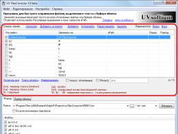
Src="https://present5.com/presentation/-29367016_63610977/image-15.jpg" alt="(!LANG:Program Broadcast to Microsoft visual studio 2005 1) Create a project by selecting the menu File->New->Project and"> Program Translation in Microsoft Visual Studio 2005 1) Create a project by selecting the menu File->New->Project and specifying the project name (hello.prj) and type project: Win 32 Project. additional options project wizard to specify “Empty Project”.
Src="https://present5.com/presentation/-29367016_63610977/image-16.jpg" alt="(!LANG:Program translation in Microsoft Visual Studio 2005 2) In the project tree (View->Solution Explorer) add"> Трансляция программы в Microsoft Visual Studio 2005 2) В дереве проекта (View->Solution Explorer) добавить файл, в котором будет содержаться текст программы: Source. Files->Add->New. Item.!}
 Translation of the program in Microsoft Visual Studio 2005 3) Select the Code C++ file type, but specify the name with the extension. asm:

 Translation of the program in Microsoft Visual Studio 2005 5) Set compiler options. Select on the right button in the project file menu Custom Build Rules…
 Translation of the program in Microsoft Visual Studio 2005 and in the window that appears, select Microsoft Macro Assembler.
 Translation of the program in Microsoft Visual Studio 2005 Check by right button in the file hello. asm of the project tree from the Properties menu and set General->Tool: Microsoft Macro Assembler.
Src="https://present5.com/presentation/-29367016_63610977/image-22.jpg" alt="(!LANG:Program translation in Microsoft Visual Studio 2005 6) Compile the file by selecting Build->Build hello.prj."> Трансляция программы в Microsoft Visual Studio 2005 6) Откомпилировать файл, выбрав Build->Build hello. prj. 7) Запустить программу, нажав F 5 или выбрав меню Debug->Start Debugging.!}
 OS programming Windows Programming in OC Windows is based on the use of API functions (Application Program Interface, i.e. interface software application). Their number reaches 2000. The program for Windows largely consists of such calls. All interactions with external devices and resources of the operating system occurs, as a rule, through such functions. operating room Windows system uses a flat memory model. The address of any memory location will be determined by the contents of one 32-bit register. There are 3 types of program structures for Windows: dialog (the main window is a dialog), console or windowless structure, classical structure (window, frame).
 Call Windows features API In the help file, any API function is represented as type function_name (FA 1, FA 2, FA 3) Type – return value type; FAX – list of formal arguments in their order. For example, int Message. Box (HWND h. Wnd, LPCTSTR lp. Text, LPCTSTR lp. Caption, UINT u. Type); This function displays a window with a message and an exit button(s). Meaning of parameters: h. Wnd - handle to the window in which the message window will appear, lp. Text - the text that will appear in the window, lp. Caption - text in the window title, u. Type - window type, in particular, you can specify the number of exit buttons.
 Calling Windows API functions int Message. Box (HWND h. Wnd, LPCTSTR lp. Text, LPCTSTR lp. Caption, UINT u. Type); Almost all API function parameters are actually 32-bit integers: HWND is a 32-bit integer, LPCTSTR is a 32-bit string pointer, UINT is a 32-bit integer. The suffix "A" is often added to the name of functions to jump to newer versions of functions.
 Calling Windows API functions int Message. Box (HWND h. Wnd, LPCTSTR lp. Text, LPCTSTR lp. Caption, UINT u. Type); When using MASM, you must add @N N at the end of the name - the number of bytes that the passed arguments occupy on the stack. For Win 32 API functions, this number can be defined as the number of arguments n times 4 (bytes in each argument): N=4*n. To call a function, the CALL instruction of the assembler is used. In this case, all arguments to the function are passed to it via the stack (PUSH command). Argument passing direction: LEFT TO RIGHT - BOTTOM UP. Argument u will be pushed onto the stack first. type. Call specified function will look like this: CALL Message. box. [email protected]
 Calling Windows API functions int Message. Box (HWND h. Wnd, LPCTSTR lp. Text, LPCTSTR lp. Caption, UINT u. Type); The result of executing any API function is usually an integer, which is returned in the EAX register. The OFFSET directive is a "segment offset" or, in high-level language terms, a "pointer" to the start of a string. The EQU directive, like #define in C, defines a constant. The EXTERN directive tells the compiler that a function or identifier is external to the module.
 An example of the program "Hello everyone!" . 686 P. MODEL FLAT, STDCALL. STACK 4096. DATA MB_OK EQU 0 STR 1 DB "My first program", 0 STR 2 DB "Hello everyone!", 0 HW DD ? EXTERN message. box. [email protected]: NEAR. CODE START: PUSH MB_OK PUSH OFFSET STR 1 PUSH OFFSET STR 2 PUSH HW CALL Message. box. [email protected] RET END START
 The INVOKE directive The MASM language translator also makes it possible to simplify the function call using a macro tool - the INVOKE directive: INVOKE function, parameter1, parameter2, ... There is no need to add @16 to the function call; the parameters are written exactly in the order in which they are given in the function description. translator macros push parameters onto the stack. to use the INVOKE directive, you must have a description of the function prototype using the PROTO directive in the form: Message. box. A PROTO: DWORD, : DWORD
By purpose, commands can be distinguished (examples of mnemonic opcodes of commands of a PC assembler such as IBM PC are given in brackets):
l execution arithmetic operations(ADD and ADC - additions and additions with carry, SUB and SBB - subtractions and subtractions with borrowing, MUL and IMUL - unsigned and signed multiplications, DIV and IDIV - unsigned and signed divisions, CMP - comparisons, etc. .);
l performing logical operations (OR, AND, NOT, XOR, TEST, etc.);
l data transfer (MOV - send, XCHG - exchange, IN - enter into the microprocessor, OUT - withdraw from the microprocessor, etc.);
l control transfer (program branches: JMP - unconditional branch, CALL - procedure call, RET - return from procedure, J * - conditional branch, LOOP - loop control, etc.);
l processing character strings (MOVS - transfers, CMPS - comparisons, LODS - downloads, SCAS - scans. These commands are usually used with a prefix (repetition modifier) REP;
l program interrupts (INT - software interrupts, INTO - conditional interrupts on overflow, IRET - return from interrupt);
l microprocessor control (ST* and CL* - set and clear flags, HLT - stop, WAIT - standby, NOP - idle, etc.).
WITH complete list assembler commands can be found in the works.
Data transfer commands
l MOV dst, src - data transfer (move - move from src to dst).
Transfers: one byte (if src and dst are in byte format) or one word (if src and dst are in word format) between registers or between register and memory, and writes an immediate value to a register or memory.
The operands dst and src must have the same format - byte or word.
Src can be of type: r (register) - register, m (memory) - memory, i (impedance) - immediate value. Dst can be of type r, m. Operands cannot be used in one command: rsegm together with i; two operands of type m and two operands of type rsegm). Operand i can be simple expression:
mov AX, (152 + 101B) / 15
Expression evaluation is performed only during translation. Flags do not change.
l PUSH src - putting a word on the stack (push - push through; push to the stack from src). Pushes the contents of src onto the top of the stack - any 16-bit register (including segment) or two memory locations containing a 16-bit word. The flags do not change;
l POP dst - extracting a word from the stack (pop - pop; count from the stack in dst). Removes a word from the top of the stack and places it in dst - any 16-bit register (including segment) or two memory locations. Flags do not change.
Introduction.
The language in which the original program is written is called input language, and the language into which it is translated for execution by the processor - weekend language. The process of converting an input language into an output language is called broadcast. Since processors are capable of executing programs in binary machine language, which is not used for programming, translation of all source programs is necessary. known two ways translations: compilation and interpretation.
At compilation the source program is first completely translated into an equivalent program in the target language, called object program and then executed. This process is carried out using a special programs, called compiler. A compiler for which the input language is a symbolic representation of the machine (output) language of binary codes is called assembler.
At interpretations each line of source program text is parsed (interpreted) and the command specified in it is immediately executed. The implementation of this method lies with interpreter program. Interpretation takes a long time. To increase its efficiency, instead of processing each line, the interpreter preliminarily converts all command strings to characters (
). The generated sequence of symbols is used to perform the functions assigned to the original program.
The assembly language discussed below is implemented using compilation.
Features of the language.
The main features of the assembler:
● instead of binary codes, the language uses symbolic names - mnemonics. For example, for the addition command (
) mnemonic is used
Subtractions (
multiplication (
Divisions (
etc. Symbolic names are also used to address memory cells. To program in assembly language, instead of binary codes and addresses, you need to know only the symbolic names that the assembler translates into binary codes;
● each statement corresponds one machine command(code), that is, there is a one-to-one correspondence between machine instructions and operators in an assembly language program;
● language provides access to all objects and teams. High-level languages do not have this ability. For example, assembly language allows you to check a flag register bit, and a high-level language (for example,
) does not have this capability. Note that languages for systems programming (for example, C) often occupy an intermediate position. In terms of accessibility, they are closer to assembly language, but they have the syntax of a high-level language;
● assembly language is not a universal language. Each specific group of microprocessors has its own assembler. High-level languages do not have this disadvantage.
Unlike high-level languages, writing and debugging an assembly language program takes a lot of time. Despite this, assembly language has become wide use due to the following circumstances:
● A program written in assembly language is much smaller and much faster than a program written in a high-level language. For some applications, these indicators play a paramount role, for example, many system programs(including compilers), programs in credit cards, cell phones, device drivers, etc.;
● some procedures require full access to hardware, which is usually not possible in a high-level language. This case includes interrupts and interrupt handlers in operating systems, as well as device controllers in real-time embedded systems.
In most programs, only a small percentage of the total code is responsible for a large percentage of the program's execution time. Typically, 1% of the program is responsible for 50% of the execution time, and 10% of the program is responsible for 90% of the execution time. Therefore, to write a specific program in real conditions, both assembler and one of the high-level languages are used.
Operator format in assembly language.
An assembly language program is a list of commands (statements, sentences), each of which occupies a separate line and contains four fields: a label field, an operation field, an operand field, and a comment field. Each field has a separate column.
Label field.
Column 1 is allocated for the label field. A label is a symbolic name, or identifier, addresses memory. It is necessary in order to be able to:
● make a conditional or unconditional transition to the command;
● get access to the place where the data is stored.
Such statements are labeled. To designate a name, (capital) letters of the English alphabet and numbers are used. The name must start with a letter and end with a colon. The colon label can be written on a separate line, and the opcode can be written on the next line in column 2, which simplifies the work of the compiler. The absence of a colon makes it impossible to distinguish between a label and an opcode if they are on separate lines.
In some versions of assembly language, colons are placed only after instruction labels, not after data labels, and label length can be limited to 6 or 8 characters.
The label field should not contain the same names, since the label is associated with the addresses of commands. If during program execution there is no need to call a command or data from memory, then the label field remains empty.
Transaction code field.
This field contains the command mnemonic or pseudo-command (see below). The command mnemonic code is chosen by the language designers. In assembly language
mnemonic selected to load register from memory
), and to store the contents of the register in memory - the mnemonic
). In assembly languages
you can use the same name for both operations, respectively
If the choice of mnemonic names can be arbitrary, then the need to use two machine instructions is due to the processor architecture
Register mnemonics also depend on the assembler version (Table 5.2.1). 
Operand field.
Here is the additional information required to perform the operation. In the field of operands for jump instructions, the address where you want to jump is indicated, as well as addresses and registers that are operands for the machine instruction. As an example, here are the operands that can be used for 8-bit processors
● numerical data,
presented in different number systems. To indicate the number system used, the constant is followed by one of the Latin letters: B,
Accordingly, binary, octal, hexadecimal, decimal number systems (
may not be recorded). If the first digit of the hexadecimal number is A, B, C,
Then an insignificant 0 (zero) is added in front;
● codes of microprocessor internal registers and memory cells
M (sources or receivers of information) in the form of letters A, B, C,
M or their addresses in any number system (for example, 10V - register address
in binary system);
● identifiers,
for registered aircraft pairs,
The first letters B
H; for a pair of accumulator and feature register -
; for the program counter -
; for stack pointer -
● labels indicating addresses of operands or next instructions in conditional
(when the condition is met) and unconditional transitions. For example, operand M1 in the command
means the need for an unconditional transition to the command, the address of which in the label field is marked with the identifier M1;
● expressions,
which are built by linking the data discussed above using arithmetic and logical operators. Note that the way data space is reserved depends on the version of the language. Assembly language developers for
Define the word), and later introduced an alternative.
which from the very beginning was in the language for processors
In language version
used
define a constant).
Processors process operands of different lengths. To define it, assembler developers have made different decisions, for example:
II registers of different lengths have different names: EAX - for placing 32-bit operands (type
); AX - for 16-bit (type
and AN - for 8-bit (type
● for processors
suffixes are added to each opcode: suffix
For type
; suffix ".B" for type
for operands of different lengths, different opcodes are used, for example, to load a byte, a halfword (
) and words in 64-bit register use opcodes
respectively.
Comments field.
This field provides explanations about the actions of the program. Comments do not affect the operation of the program and are intended for a person. They may be needed to modify a program that, without such comments, may be completely incomprehensible even to experienced programmers. A comment begins with a character and is used to explain and document programs. The start character of a comment can be:
● semicolon (;) in languages for processors of the company
● exclamation mark (!) in languages for
Each separate line reserved for a comment is preceded by a start character.
Pseudo commands (directives).
In assembly language, two main types of commands can be distinguished:
● basic instructions that are equivalent to the machine code of the processor. These commands do all the processing provided by the program;
● pseudo-commands or directives, designed to serve the process of translating the program into the language of code combinations. As an example, in Table. 5.2.2 shows some pseudo-commands from the as-assembler
for family
. 
When programming, there are situations when, according to the algorithm, the same chain of commands must be repeated many times. To get out of this situation, you can:
● write the desired sequence of commands whenever it occurs. This approach leads to an increase in the volume of the program;
● arrange this sequence into a procedure (subroutine) and call it if necessary. Such an exit has its drawbacks: each time you have to execute a special procedure call instruction and a return instruction, which, with a short and frequently used sequence, can greatly reduce the speed of the program.
The most simple and effective method repeated repetition of a chain of commands is to use macro, which can be thought of as a pseudo-command designed to re-translate a group of commands frequently encountered in a program.
A macro, or macro instruction, is characterized by three aspects: macro definition, macro inversion, and macro expansion.
macro definition
This is a designation for a repeatedly repeated sequence of program commands, used for references in the text of the program.
A macro has the following structure:
List of expressions; macro definition
There are three parts to the above macro definition structure:
● header
macro containing the name
Pseudo-command
and a set of parameters;
● dotted body macro;
● team
graduation
macro definitions.
A macro parameter set contains a list of all parameters given in the operand field for the selected instruction group. If these parameters are given earlier in the program, then they can be omitted in the macro definition header.
For reassembly of the selected group of instructions, a call is used, consisting of the name
macro and parameter list with other values.
When the assembler encounters a macro definition during compilation, it stores it in the macro definition table. With subsequent appearances in the program of the name (
) of a macro, the assembler replaces it with the body of the macro.
Using a macro name as an opcode is called macro-reversal(macro call), and its replacement by the body of the macro - macro expansion.
If the program is represented as a sequence of characters (letters, numbers, spaces, punctuation and carriage returns to jump to new line), then macro expansion consists in replacing some chains from this sequence with other chains.
Macro expansion occurs during the assembly process, not during program execution. Ways to manipulate strings of characters is assigned to macro tools.
The assembly process is carried out in two passes:
● On the first pass, all macro definitions are kept and macro calls are expanded. In this case, the source program is read and converted into a program in which all macro definitions are removed, and each macro call is replaced by a macro body;
● The second pass processes the received program without macros.
Macros with parameters.
To work with repeating sequences of commands, the parameters of which can take on different values, macro definitions are provided:
● with actual parameters that are placed in the operand field of the macro call;
● with formal parameters. During macro expansion, each formal parameter that appears in the body of the macro is replaced by the corresponding actual parameter.
using macros with parameters.
Program 1 shows two similar sequences of commands, differing in that the first of them swaps P and
And the second
Program 2 includes a macro with two formal parameters P1 and P2. During macro expansion, each P1 character inside the macro body is replaced by the first actual parameter (P,
), and the symbol P2 is replaced by the second actual parameter (
) from program No. 1. In a macro call
program 2 is marked: P,
The first actual parameter,
The second actual parameter.
Program 1
Program 2
MOV EBX,Q MOV EAX,Pl
MOV Q,EAX MOV EBX,P2
MOV P,EBX MOV P2,EAX
Extended capabilities.
Consider some advanced features of the language
If a macro containing a conditional branch instruction and a label to jump to is called two or more times, the label will be duplicated (label duplication problem), which will cause an error. Therefore, each call is assigned (by the programmer) a separate label as a parameter. In language
the label is declared local (
) and thanks to the advanced features, the assembler automatically generates a different label each time the macro is expanded.
allows you to define macros inside other macros. This advanced feature is very useful when combined with conditional program linking. Consider
IF WORDSIZE GT 16 M2 MACRO
Macro M2 can be defined in both parts of the statement
However, the definition depends on whether the program is being assembled on a 16-bit or 32-bit processor. If M1 is not called, then macro M2 will not be defined at all.
Another advanced feature is that macros can call other macros, including themselves - recursive call. In the latter case, in order to avoid an infinite loop, the macro must pass a parameter to itself, which changes with each expansion, and also check this parameter and end the recursion when the parameter reaches a certain value.
On the use of macros in assembler.
When using macros, the assembler must be able to perform two functions: save macro definitions and expand macro calls.
Saving macro definitions.
All macro names are stored in a table. Each name is accompanied by a pointer to the corresponding macro so that it can be called if necessary. Some assemblers have a separate table for macro names, others have a common table in which, along with macro names, there are all machine commands and directives.
When encountering a macro during assembly created:
● new table element with the name of the macro, the number of parameters and a pointer to another macro definition table where the macro body will be stored;
● list formal parameters.
The body of the macro, which is simply a string of characters, is then read and stored in the macro definition table. Formal parameters occurring in the loop body are marked with a special symbol.
Internal representation of a macro
from the above example for program 2 (p. 244) is:
MOV EAX, MOV EBX, MOV MOV &
where the semicolon is used as the carriage return character, and the ampersand & is used as the formal parameter character.
Macro call extension.
Whenever a macro definition is encountered during assembly, it is stored in the macro table. When a macro is called, the assembler temporarily suspends reading input data from the input device and starts reading the saved macro body. The formal parameters extracted from the macro body are replaced by the actual parameters and provided by the call. An ampersand & in front of the parameters allows the assembler to recognize them.
Although there are many versions of assembler, assembly processes have common features and are similar in many ways. The work of a two-pass assembler is considered below.
Two pass assembler.
The program consists of a number of statements. Therefore, it would seem that the following sequence of actions can be used during assembly:
● translate it into machine language;
● transfer the received machine code to a file, and the corresponding part of the listing - to another file;
● repeat the above procedures until the entire program is broadcast.
However, this approach is not efficient. An example is the so-called problem leading link. If the first statement is a jump to the P statement at the very end of the program, then the assembler cannot translate it. He must first determine the address of the operator P, and for this it is necessary to read the entire program. Each complete reading of the original program is called passage. Let's show how we can solve the forward reference problem using two passes:
● on the first pass collect and store all symbol definitions (including labels) in the table, and on the second pass, read and assemble each operator. This method is relatively simple, but the second pass through the original program requires additional I/O time;
● on the first pass, convert program into an intermediate form and save it in a table, and the second pass is performed not according to the original program, but according to the table. This method of assembly saves time, since no I/O operations are performed on the second pass.
First pass.
Purpose of the first pass- build a symbol table. As noted above, another goal of the first pass is to save all macro definitions and expand the calls as they appear. Therefore, both character definition and macro expansion occur in the same pass. The symbol can be either label, or meaning, which is assigned a specific name using the -you directive:
;Value - buffer size 
By giving meaning to the symbolic names in the instruction label field, the assembler essentially sets the addresses that each instruction will have during program execution. To do this, the assembler during the assembly process saves instruction address counter(
) as a special variable. At the beginning of the first pass, the value of the special variable is set to 0 and incremented after each command processed by the length of that command. As an example, in Table. 5.2.3 shows a fragment of the program indicating the length of commands and counter values. Tables are generated during the first pass symbol names, directives and operation codes, and if necessary literal table. A literal is a constant for which the assembler automatically reserves memory. We note right away that modern processors contain instructions with direct addresses, so their assemblers do not support literals. 
Symbol table
contains one element for each name (Table 5.2.4). Each entry in the symbol table contains the name itself (or a pointer to it), its numerical value, and sometimes some additional information, which may include:
● the length of the data field associated with the symbol;
● memory remapping bits (which indicate whether the value of a symbol changes if the program is loaded at a different address than the assembler intended);
● information about whether the symbol can be accessed from outside the procedure.
Symbolic names are labels. They can be specified using operators (for example,
Table of directives.
This table lists all the directives, or pseudo-commands, that occur when assembling a program.
Operation code table.
For each opcode, the table has separate columns: opcode designation, operand 1, operand 2, hexadecimal value of the opcode, instruction length and instruction type (Table 5.2.5). Operation codes are divided into groups depending on the number and type of operands. The command type determines the group number and specifies the procedure that is called to process all commands in that group. 
Second pass.
Purpose of the second pass- creating an object program and printing, if necessary, an assembly protocol; output information needed by the linker to link procedures that were assembled at different times into one executable file.
In the second pass (as in the first), the lines containing the statements are read and processed one after the other. The original operator and the output derived from it in hexadecimal object the code can be printed or buffered for later printing. After resetting the command address counter, the command is called next statement.
The original program may contain errors, for example:
● the given symbol is not defined or defined more than once;
● The opcode is represented by an invalid name (due to a typo), not provided with enough operands, or has too many operands;
● no operator
Some assemblers may detect an undefined symbol and replace it. However, in most cases, when a statement with an error is found, the assembler displays an error message on the screen and tries to continue the assembly process.
Articles dedicated to the assembly language.