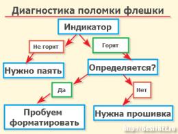
Classification of switches according to the possibility of management. Types of switches
Unmanaged switch suitable for building home network or small office networks. Its difference from the rest is the "boxed" version. That is, after the purchase, it is enough to set up a connection to the provider's server and you can distribute the Internet.
When working with such a switch, it should be borne in mind that short-term delays are possible when using voice communication pagers (Skype, Vo-IP) and the impossibility of distributing the width of the Internet channel. That is, when you turn on the Torrent program on one of the computers on the network, it will consume almost the entire bandwidth, and the rest of the computers on the network will use the rest of the bandwidth.
A managed switch is the best solution for building a network in offices and computer clubs. This type sold as standard and standard settings.
To configure such a switch, you will have to sweat - a large number of settings can turn your head, but with the right approach bring wonderful results. main feature- distribution of channel width and setting the throughput of each port. Let's take as an example an Internet channel of 50 Mbps/s, 5 computers on the network, an IP-TV set-top box and an ATC. We can do several options, but I will consider only one.
Further - only your imagination and non-standard thinking. In total, we have a relatively large channel. Why relatively? You will learn this information further if you carefully delve into the essence. I forgot to clarify - I'm building a network for a small office. IP-TV is used for the TV in the waiting room, computers - for e-mail, document transfer, website browsing, ATC - for connecting landlines to the main line to receive calls from Skype, QIP, cell phones, etc.
A managed switch is a modification of a conventional, unmanaged switch.
In addition to the ASIC chip, it contains a microprocessor capable of performing additional operations on frames, such as filtering, modification and prioritization, as well as other actions not related to frame forwarding. For example, provide a user interface.
In practical terms, the differences between managed switches and unmanaged ones are, firstly, in the list of supported standards - if a regular, unmanaged switch only supports the Ethernet standard (IEEE 802.3) in its various varieties, then managed switches support a much wider list of standards: 802.1Q. 802.1X, 802.1AE, 802.3ad (802.1AX) and so on that require configuration and management.
There is another type - SMART switches.
The appearance of smart switches was due to a marketing ploy - devices support a significantly smaller number of functions than their older counterparts, but nevertheless they are manageable.
In order not to confuse and mislead consumers, the first models were produced with the designation intelligent or web-managed.
These devices at a much lower cost offered the basic functionality of managed switches - VLAN organization, administrative enabling and disabling of ports, filtering by MAC address or rate limiting. Traditionally, the only management method was a web interface, so the name web-emanaged has firmly stuck to smart switches.
The switch stores in associative memory a switching table that indicates the correspondence of the MAC address of the host to the port of the switch. When the switch is powered on, this table is empty and it starts in learning mode. In this mode, incoming data on any port is transmitted to all other ports of the switch. In this case, the switch analyzes the frames (frame) and, having determined the MAC address of the sending host, enters it into the table.
Subsequently, if one of the switch ports receives a frame destined for a host whose MAC address is already in the table, then this frame will be transmitted only through the port specified in the table. If the MAC address of the destination host is not bound to any switch port, then the frame will be sent to all ports.
Over time, the switch builds a complete table for all its ports, and as a result, traffic is localized.
It is worth noting the low latency (delay) and high forwarding speed on each interface port.
Switching methods in the switch.
There are three ways to switch. Each of them is a combination of parameters such as "switch decision" latency (latency) and transmission reliability.
With intermediate storage (Store and Forward).
"Along" (cut-through).
"Fragment-free" or hybrid.
With intermediate storage (Store and Forward). The switch reads all the information received in the frame, checks it for errors, selects a switching port, and then sends a verified frame to it.
"Along" (cut-through). The switch reads only the destination address in the frame and then switches. This mode reduces transmission delays, but it does not have an error detection method.
"Fragment-free" or hybrid. This mode is a modification of the "Running through" mode. Transmission is carried out after filtering fragments of collisions (frames of 64 bytes in size are processed using the store-and-forward technology, the rest are processed using the cut-through technology). The "switch decision" delay is added to the time it takes for a frame to enter and leave the switch port, and together with it determines the overall delay of the switch.
Switch performance characteristics.
The main characteristics of a switch that measure its performance are:
- - speed of filtration (filtering);
- - routing speed (forwarding);
- - bandwidth (throughput);
- - frame transmission delay.
In addition, there are several switch characteristics that have the greatest impact on these performance characteristics. These include:
- - size of the frame buffer(s);
- - performance of the internal bus;
- - performance of the processor or processors;
- - size of the internal address table.
The rate of filtering and frame advancement are the two main performance characteristics of the switch. These characteristics are integral indicators, they do not depend on how the switch is technically implemented.
The filter rate determines the rate at which the switch performs the following frame processing steps:
- - receiving a frame in its buffer;
- - Destruction of the frame, since its destination port is the same as the source port.
The forward rate determines the rate at which the switch performs the following frame processing steps:
- - receiving a frame in its buffer;
- - viewing the address table in order to find the port for the destination address of the frame;
- - frame transmission to the network through the destination port found in the address table.
Both filtration rate and advance rate are usually measured in frames per second.
If the characteristics of the switch do not specify for which protocol and for which frame size the values of filtering and forwarding rates are given, then by default it is considered that these indicators are given for the Ethernet protocol and frames 64 bytes long (without preamble), with a data field of 46 bytes .
The use of frames of minimum length as the main indicator of the speed of the switch is explained by the fact that such frames always create the most difficult operating mode for the switch compared to frames of a different format with equal throughput of the transferred user data.
Therefore, when testing a switch, the minimum frame length mode is used as the most difficult test, which should check the ability of the switch to work with the worst combination of traffic parameters for it.
In addition, for packets of a minimum length, the filtering and forwarding speeds have a maximum value, which is of no small importance when advertising a switch.
The throughput of a switch is measured by the amount of user data transmitted per unit of time through its ports.
Since the switch operates at the link layer, the user data for it is the data that is carried in the data field of the frames of the link layer protocols - Ethernet, Token Ring, FDDI, etc.
The maximum value of the switch throughput is always achieved on frames of maximum length, since in this case the share of overhead costs for service information frame is much lower than for frames of the minimum length, and the time the switch performs frame processing operations per byte user information, much less.
The dependence of the switch throughput on the size of transmitted frames is well illustrated by the example of the Ethernet protocol, for which, when transmitting frames of the minimum length, a transmission rate of 14880 frames per second and a throughput of 5.48 Mb / s is achieved, and when transmitting frames of the maximum length, a transmission rate of 812 frames per second is achieved. second and a throughput of 9.74 Mb/s.
Throughput drops by almost half when switching to frames of the minimum length, and this is without taking into account the time lost on processing frames by the switch.
Frame transmission delay is measured as the time elapsed from the moment the first byte of the frame arrives at the input port of the switch until the moment this byte arrives at the output port of the switch.
The latency is the sum of the time spent buffering the bytes of the frame, as well as the time spent processing the frame by the switch - looking up the address table, deciding whether to filter or forward, and gaining access to the egress port media. The amount of delay introduced by the switch depends on the mode of its operation. If switching is carried out "on the fly", then the delays are usually small and range from 10 µs to 40 µs, and with full frame buffering - from 50 µs to 200 µs (for frames of the minimum length). The switch is a multiport device, therefore, it is customary for it to give all the above characteristics (except for the frame transmission delay) in two versions:
- - the first option - the total performance of the switch with simultaneous transmission of traffic through all its ports;
- - the second option is the performance per one port.
Since when traffic is transmitted simultaneously by several ports, there is a huge number of traffic options that differ in the size of frames in the stream, the distribution of the average intensity of frame streams between destination ports, the coefficients of variation in the intensity of frame streams, etc., etc.
Then, when comparing switches in terms of performance, it is necessary to take into account for which traffic variant the published performance data were obtained. Some laboratories that constantly test communication equipment have developed detailed descriptions of the test conditions for switches and use them in their practice, but these tests have not yet become general industrial. Ideally, a switch installed in a network transmits frames between nodes connected to its ports at the rate at which nodes generate these frames, without introducing additional delays and without losing a single frame.
In real practice, the switch always introduces some delays in the transmission of frames, and may also lose some frames, that is, not deliver them to their destinations. Due to differences in internal organization different models switches, it is difficult to predict how a particular switch will transmit frames of a particular traffic pattern. The best criterion is still the practice when the switch is placed in real network and the delays it introduces and the number of lost frames are measured. The overall performance of the switch is ensured by the sufficiently high performance of each of its individual elements - the port processor, switching matrix, common bus connecting modules, etc.
Regardless of the internal organization of the switch and how its operations are pipelined, it is possible to determine fairly simple performance requirements for its elements that are necessary to support a given traffic matrix. Because switch manufacturers strive to make their devices as fast as possible, the overall internal throughput of a switch is often marginally higher than the average of any traffic that can be routed to the switch ports according to their protocols.
This type of switches is called non-blocking, i.e., any type of traffic is transmitted without reducing its intensity. In addition to bandwidth individual elements switch, such as port processors or a shared bus, switch performance is affected by switch parameters such as the size of the address table, the size of the shared buffer or individual port buffers.
The size of the address table affects the maximum capacity of the address table and determines the maximum number of MAC addresses that the Switch can handle at the same time.
Since switches most often use a dedicated processor unit with its own memory to store an instance of the address table to perform the operations of each port, the size of the address table for switches is usually given per port.
Instances of the address table of different processor modules do not necessarily contain the same address information - most likely there will not be so many duplicate addresses, unless the traffic distribution of each port is completely equally probable among the other ports. Each port only stores the sets of addresses it has recently used. The value of the maximum number of MAC addresses that the port processor can remember depends on the application of the switch. Workgroup switches typically only support a few addresses per port, as they are designed to form microsegments. Departmental switches should support several hundred addresses, and network backbone switches up to several thousand, typically 4,000 to 8,000 addresses. Insufficient address table capacity can slow down the switch and flood the network with excess traffic. If the port processor's address table is full, and it encounters a new source address in an incoming packet, it must evict any old address from the table and place a new one in its place. This operation itself will take some time from the processor, but the main performance loss will be observed when a frame arrives with a destination address that had to be removed from the address table.
Since the frame's destination address is unknown, the switch must forward the frame to all other ports. This operation will create unnecessary work for many port processors, in addition, copies of this frame will also fall on those network segments where they are completely optional. Some switch manufacturers solve this problem by changing the algorithm for handling frames with an unknown destination address. One of the switch ports is configured as a trunk port, to which all frames with an unknown address are sent by default.
The switch's internal buffer memory is needed to temporarily store data frames in cases where they cannot be immediately transmitted to the output port. The buffer is designed to smooth out short-term traffic ripples.
After all, even if the traffic is well balanced and the performance of the port processors, as well as other processing elements of the switch, is sufficient to transfer average traffic values, this does not guarantee that their performance will be enough for very high peak load values. For example, traffic can arrive simultaneously at all switch inputs for several tens of milliseconds, preventing it from transmitting received frames to output ports. To prevent frame losses in case of short-term multiple excess of the average traffic intensity value (and for local networks often there are values of the traffic ripple factor in the range of 50-100) the only remedy is a large buffer. As in the case of address tables, each port processor module usually has its own buffer memory for storing frames. The larger the amount of this memory, the less likely it is to lose frames during congestion, although if the traffic averages are unbalanced, the buffer will still overflow sooner or later.
Typically, switches designed to operate in critical parts of the network have a buffer memory of several tens or hundreds of kilobytes per port.
It's good that this buffer memory can be reallocated between multiple ports, since simultaneous overloads on multiple ports are unlikely. An additional security feature can be a common buffer for all ports in the switch management module. Such a buffer is usually several megabytes in size.
General classification of switches
Computer A network is a group of computers connected to each other by a communication channel. The channel provides data exchange within the network, that is, data exchange between computers in a given group. The network may consist of two or three computers, or it may unite several thousand PCs. Physically, data exchange between computers can be carried out over a special cable, fiber optic cable, or through twisted pair.
Network hardware and hardware and software help to connect computers in a network and ensure their interaction. These resources can be divided into following groups according to their main functional purpose:
passive network hardware connectors, cables, patch cords, patch panels, telecommunication sockets, etc.;
Active network equipment converters / adapters, modems, repeaters, bridges, switches, routers, etc.
Currently, the development of computer networks occurs in the following areas:
Increase in speed;
Implementation of segmentation based switching;
Connecting networks using routing.
Layer 2 switching
Considering the properties of the second level of the ISO/OSI reference model and its classical definition, one can see that given level belongs to the main part of the commuting properties.
The link layer provides reliable data transit through the physical channel. In particular, it addresses issues of physical addressing (as opposed to network or logical addressing), network topology, linear discipline (how end system use network channel), fault notification, orderly delivery of data blocks, and information flow control.
In fact, the functionality defined by the link layer of the OSI model serves as a platform for some of today's most powerful technologies. The great importance of layer 2 functionality is highlighted by the fact that equipment manufacturers continue to invest heavily in the development of devices with such functionality, i.e. switches.
Layer 3 switching
Switching at the third level? it's hardware routing. Traditional routers implement their functions using software-controlled processors, which we will call software routing. Traditional routers typically forward packets at about 500,000 packets per second. Layer 3 switches today operate at speeds up to 50 million packets per second. Its further increase is possible, since each interface module, as in the second layer switch, is equipped with its own ASIC-based packet forwarding processor. So increasing the number of modules leads to an increase in routing performance. The use of high-speed large scale custom integrated circuit (ASIC) technology is the main feature that distinguishes Layer 3 switches from traditional routers.
A switch is a device that operates at the second/third layer of the ISO/OSI reference model and is designed to combine network segments operating on the basis of a single link/network layer protocol. The switch routes traffic through only the one port required to reach the destination.
The figure (see Figure 1) shows the classification of switches by management capabilities and according to the ISO/OSI reference model.
Figure 1 Classification of switches
Let us consider in more detail the purpose and capabilities of each type of switch.
Unmanaged switch? is a device designed to connect multiple nodes computer network within one or more network segments. It transmits data only directly to the recipient, with the exception of broadcast traffic to all network nodes. An unmanaged switch cannot perform any other functions.
Managed switches are more complex devices that allow you to perform a set of functions of the second and third layers of the ISO / OSI model. They can be managed through the web interface, command line via the console port or remotely via the SSH protocol, as well as using the SNMP protocol.
Configurable switches provide users with the ability to configure certain settings through simple utilities management, web interface, simplified command line interface and SNMP protocol.
Layer 2 switches parse incoming frames, decide on their forwarding, and forward them to their destinations based on the MAC addresses of the OSI model's link layer. The main advantage of layer 2 switches is transparency for upper layer protocols. Since the switch operates at the second layer, it does not need to analyze the information of the upper layers of the OSI model.
Layer 3 switches perform switching and filtering based on the addresses of the link (layer 2) and network (layer 3) layers of the OSI model. Such switches dynamically decide whether to switch (layer 2) or route (layer 3) incoming traffic. Layer 3 switches switch within working group and routing between different subnets or virtual local area networks (VLANs).
Switches are divided into managed and unmanaged (the most simple). More complex switches allow you to control switching at the channel (second) and network (third) level of the OSI model. Usually they are named accordingly, for example Layer 2 Switch or simply L2 for short. The switch can be managed via the Web interface protocol, SNMP, RMON, etc. Many managed switches allow you to perform additional functions: VLAN, QoS, aggregation, mirroring. Complex switches can be combined into one logical device - a stack, in order to increase the number of ports (for example, you can combine 4 switches with 24 ports and get a logical switch with 96 ports).
router
Router or router - specialized network computer, which has at least two network interfaces and forwards data packets between different network segments, makes forwarding decisions based on information about the network topology and certain rules set by the administrator.
The router operates at a higher "network" layer 3 of the OSI network model than the switch (or network bridge) and hub (hub), which operate at layer 2 and layer 1 of the OSI model, respectively.
The principle of operation of the router
Typically, the router uses the destination address specified in the packet data and determines from the routing table the path over which the data should be sent. If there is no described route in the routing table for the address, the packet is dropped.
There are other ways to determine the packet forwarding path, such as using the source address, upper layer protocols used, and other information contained in network layer packet headers. Often, routers can translate the addresses of the sender and recipient, filter the transit data flow based on certain rules in order to restrict access, encrypt / decrypt the transmitted data, etc.
Subnet mask
In the terminology of TCP / IP networks, a network mask or subnet mask (network mask) is a bit mask (bitmask), which determines which part of the IP address (ip address) of the host (host) of the network refers to the network address, and which part to the address of the host itself in this network. To get the network address, knowing the IP address and subnet mask, you need to apply the bitwise conjunction operation to them. For example, in the case of a more complex mask (bit operations in IPv6 look the same):
IP address: 11000000 10101000 00000001 00000010 (192.168.1.2)
Subnet mask: 11111111 11111111 11111111 00000000 (255.255.255.0)
Network address: 11000000 10101000 00000001 00000000 (192.168.1.0)
Classless addressing is an IP addressing method that allows you to flexibly manage the IP address space without using the rigid framework of classful addressing. Using this method makes economical use of the limited resource of IP addresses, since different subnet masks can be applied to different subnets. Subnet masks are the basis of Classless Routing (CIDR). In this approach, the subnet mask is written along with the IP address in the format "IP address/number of 1 bits in mask". The number after the slash indicates the number of 1's in the subnet mask.
Subnet mask assignment
The mask is assigned according to the following scheme (for class C networks), where is the number of computers in the subnet + 2, rounded up to the next higher power of two (this formula is valid for ≤ 254, for > 254 there will be a different formula).
Example: There are 30 computers in a class C network, the mask for such a network is calculated as follows:
28 - 32 = 224 (0E0h)< = >255.255.255.224 (0xFFFFFFE0)
Local network project created in the Cisco Packet Tracer program:
Picture 1
Figure 1 shows logical construction a local network containing 16 workstations, 3 switches, 2 routers with the function of DHCP servers, 2 access points and several end devices connected to the access points.
Router settings:

Figure 2

Figure 3
Switch settings:

Figure 4

Figure 5

Figure 6
Access point settings:

Figure 7

Figure 8
Conclusion
IN modern computers processors are made in the form of a compact module (about 5×5×0.3 cm in size) inserted into a ZIF socket (AMD) or onto a spring-loaded structure - LGA (Intel). A feature of the LGA connector is that the pins are transferred from the processor case to the connector itself - the socket located on motherboard. Most modern processors are implemented as a single semiconductor chip containing millions, and more recently even billions of transistors. Modern processors use from 1 to 16 control blocks and from 4 to 64 operation blocks. In the transition to asynchronous circuitry, the use of several dozen control blocks and several hundred operational blocks will be justified. Such a transition, together with a corresponding increase in the number of blocks, will increase peak performance by more than two orders of magnitude and average performance by more than an order of magnitude.
Along with materials describing possible prospects for the production of multi-gigabit PCM chips using a 45- or 32-nm process, ST presented a prototype of a 128-Mbit PCM chip manufactured using 90-nm technology. The advantages of PRAM include small cell area, good electrical performance, and high reliability.
In the next 10-20 years, the material part of the processors will most likely change due to the fact that technological process reaches the physical limits of production. Perhaps these will be:
Optical computers - in which instead of electrical signals light streams (photons, not electrons) are processed.
Quantum computers, whose work is entirely based on quantum effects. Currently, work is underway to create working versions of quantum processors.
Molecular computers - computing systems, using the computational capabilities of molecules (mainly organic). Molecular computers use the idea of computational possibilities for the arrangement of atoms in space.
solid state drive
A solid state drive (SSD, solid-state drive) is a computer non-mechanical storage device based on memory chips. In addition to them, the SSD contains a control controller.
There are two types of solid state drives: SSD based on memory like random access memory computers, and SSD-based flash memory.
Currently, solid state drives are used in compact devices: laptops, netbooks, communicators and smartphones, but can also be used in stationary computers to improve performance. Some well-known manufacturers have switched to the production of solid state drives already completely, for example, Samsung sold the business of manufacturing hard drives Seagate company. There are also so-called hybrid hard drives, which appeared, among other things, due to the current, proportionally higher cost of solid-state drives. Such devices combine a hard drive in one device. magnetic disks(HDD) and solid state drive relatively small volume, as a cache (to increase the performance and service life of the device, reduce power consumption).
These drives are built on the use of volatile memory (the same as used in RAM personal computer) are characterized by ultra-fast reading, writing and information retrieval. Their main disadvantage is their extremely high cost. They are mainly used to speed up the work of large database management systems and powerful graphic stations. Such drives are usually equipped with batteries to save data in case of power loss, and more expensive models are equipped with backup and / or online backup systems. An example of such drives is I-RAM. Users with sufficient RAM can organize virtual machine and locate its hard drive in RAM and evaluate the performance.
Back in the first issue of LAN magazine, in the "First Lessons" section, we published an article by S. Steinke "Ethernet Switching" about the basics of this technology and we made the right choice: over the next three years, Ethernet switching has become one of the "hottest" technologies. Later, we returned to this topic more than once (see, in particular, D. Ganzhi's article "Switches in Local Area Networks" in the April 1997 issue of LAN). The first article appeared at a time when Fast Ethernet was still fighting for its place in the sun with 100VG-AnyLAN, and the outcome of the struggle was far from clear, so it was devoted primarily to switching at 10 Mbps. The second of these articles dealt mainly with the general aspects of switching. Given the above circumstances, as well as the importance of switching as such, we considered it possible and even necessary to return to this topic again, especially since the series of articles on Ethernet would not be complete without its consideration.
WHAT IS A SWITCH?
A switch is essentially a multi-port bridge, so like a bridge, it accepts incoming packets, stores them temporarily, and then forwards them to a different port based on the packet's destination address. Switches can be used to connect different LANs, to segment a LAN (ie, reduce the number of nodes competing for media in the same collision domain), and to overcome segment diameter limitations. The latter application is especially important in the case of Fast Ethernet networks, where the segment diameter cannot exceed 205 m for twisted pair cable.
Switches use the concept of a "virtual link" to establish a temporary connection between a sender and a receiver. After the packet is transmitted, the virtual connection is terminated. The switch maintains a table where it remembers which stations (more precisely, which MAC addresses) are connected to which physical port. In Figure 1, the subscriber with address A sends a packet to the recipient with address D. From the table, the switch determines that the station with address A is connected to port 1, and the station with address D is connected to port 4. Based on these data, it establishes a virtual connection to send the message between ports 1 and 4.
Picture 1.
Based on the destination address, the switch determines which port to forward the incoming packet to.
In an Ethernet switch, data transmission between non-overlapping pairs of ports can occur simultaneously. For example, node A may be sending a packet to node D at the same time node B is sending a packet to node C. Both conversations are happening at the same time, so in the case of Ethernet, the total throughput (throughput) of the switch in our example is 20 Mbps. It is determined by summing the bandwidth available for each connection, say in the case of a 12-port Ethernet switch, theoretically it is 60 Mbps. For comparison, an Ethernet repeater always has the same total throughput at 10 Mbps, regardless of the number of ports. In addition, the actual throughput of a hub can be much less when multiple devices compete for media access. However, the actual total throughput of the switch may be lower than theoretically calculated due to design flaws in the switch, such as inadequate internal bus throughput. In this case, the switch is said to have a blocking architecture.
SWITCH ARCHITECTURE
The switch architecture is determined by four main factors - port type, buffer sizes, packet forwarding mechanism, and internal bus (see Figure 2).

Figure 2.
With all the variety of switch designs, the basic architecture of these devices is determined by four components: ports, buffers, an internal bus, and a packet forwarding mechanism.
Ports can be 10 or 100 Mbps and can operate in half-duplex or full-duplex mode. Many high-end models may also contain ports for FDDI, ATM, Gigabit Ethernet, etc., but we will not touch on this topic here, especially since we already briefly considered it earlier.
The presence of buffers of sufficient capacity is of great importance for switching, in particular, in the case of using protocols in the network like a sliding window, when the subscriber acknowledges the receipt of not every packet, but a series of packets. Generally speaking, the larger the buffer capacity, the better, but the more expensive. Therefore, developers have to choose between performance and price. But they also have another solution - flow control (see below).
The packet forwarding mechanism can be one of the following three: buffered-forward switching, end-to-end switching, and hybrid end-to-end switching. We have already considered them several times, so we will only recall what they are. In the first case, the packet is completely buffered before being passed on, so this method introduces the greatest delay, but also does not allow erroneous packets to go beyond the segment. In the second case, after reading the destination address, the switch immediately forwards the frame further. As it is easy to understand, it has exactly the opposite advantages and disadvantages - low latency and the lack of adequate frame checks.
In the third case, the switch reads the first 64 bytes of the packet before passing it on. Thus, it acts as an intermediate buffered switch with respect to short frames and as an end-to-end switch with respect to long frames. Frame promotion methods are illustrated in Figure 3.
 (1x1)
(1x1)
Figure 3
Packet forwarding mechanisms differ in the point at which the packet is passed on.
The internal bus architecture determines how frames are transferred from one port to another using the switch's internal electronics. It is crucial for the efficiency of the switch: the manufacturer may claim that the internal bus has a throughput of 1-2 Gb / s, but at the same time keep silent that it is only achieved with a certain type of traffic. For example, a switch with small buffers can perform at its best only if all ports operate at the same speed and traffic is distributed evenly across all ports.
The bus can service ports cyclically or by priority. In round robin, an idle port is skipped. This architecture is best suited for cases where the traffic through each port is approximately the same. In priority service, active ports compete with each other for the internal bus. This kind of architecture is best suited when working with switches whose ports have different speeds. Some manufacturers offer switches with the ability to change the type of bus architecture.
FULL DUPLEX ETHERNET
Normal Ethernet (and Fast Ethernet) is a shared transmission medium, and all shared networks are half-duplex by definition: at a given time, only one station is allowed to transmit, and everyone else must listen. Or, to put it another way, a station can either transmit or receive, but not both at the same time.
The widespread use of four-pair wiring has opened up the fundamental possibility of transmitting and receiving data on separate paths (different pairs), which was not the case when the physical transmission medium was a coaxial cable.
In the case when only one node is connected to each switch port (we emphasize, one), there is no contention for access to the transmission medium, so no collisions can occur in principle and the CSMA / CD multiple access scheme is no longer needed.
Thus, if two nodes are connected directly to the switch ports, they can receive and transmit data simultaneously on different pairs, as a result, the theoretical throughput of such a connection is 20 Mbps in the case of Ethernet and 200 Mbps in the case of Fast Ethernet. In addition, due to the lack of competition, the actual average throughput of the connection approaches the nominal and is over 80% of the above values.
AUTOMATIC NEGOTIATION
Some switches have both 10Mbps and 100Mbps ports (see the "Congestion Prevention" section for information on how this can cause problems). Moreover, they are able to automatically determine at what speed the stations connected to it, hubs, etc. are operating. ).
The same standard RJ-45 connector can carry 10BaseT, 10BaseT full duplex, 100BaseTX, 100BaseTX full duplex, and 100BaseT4 signals. Therefore, the IEEE proposed an auto-negotiation scheme called nWAY to determine which standard the device on the other end of the cable is operating on. The order of priority for modes of operation is as follows:
- full duplex 100BaseTX;
- 100BaseT4;
- 100BaseTX;
- full duplex 10BaseT;
- 10BaseT.
In auto-negotiation, "contracting parties" use a 10BaseT analogue of Link Integrity pulses called Fast Link Pulse. Both devices send such pulses, and each of them determines in which of the transmission modes the other side is capable of operating.
Many switches support all five possible modes, so even if the connected node does not have auto-negotiation, the switch port will communicate with it on that top speed which he is capable of. In addition, the implementation of this function is very simple and does not lead to any noticeable increase in the cost of equipment. Finally, the standard provides an option to disable auto-negotiation, so that the user can set desired mode transfer manually if necessary.
OVERLOAD PREVENTION
Switches often need to bridge between 10 and 100 Mbps ports, for example, when the switch has one high-speed server port and a number of 10 Mbps ports for workstations. In the case when traffic is transmitted from a port at 10 Mbps to a port at 100 Mbps, there are no problems, but if the traffic goes in the opposite direction ... Data flow at 100 Mbps
is an order of magnitude larger than a 10Mbps port, so the switch must store excess data in its internal buffers if it has enough memory to do so. For example, suppose the first port is connected to a server with a 100 Mbps card, and the second port is connected to a client with a 10 Mbps card. If the server sends 16 consecutive packets to the client one after the other, then together they amount to an average of 24 KB of data. The transmission of a 1.5 KB frame takes 122 µs for Fast Ethernet and 1220 µs for Ethernet. Thus, the first port will receive ten frames before one frame can be sent through the second port, i.e. the first port must have a buffer of at least 24 KB. However, if the stream is long enough, then no buffers will be enough. One way to avoid congestion is to manage threads. The concept of flow control (or congestion avoidance) involves inducing an artificial collision on a high-speed port, as a result of which the sender suspends data transmission for some time in accordance with the exponential backoff algorithm. In our example, the first port will detect that its buffer is full and will send a congestion message back to the sender. The latter will take this message as a collision and stop the transmission. The switch will continue to send congestion messages until the buffer is free. This kind of flow control is performed only by switches with half-duplex ports.
SWITCH MANAGEMENT
Switch control is one of the biggest challenges facing both equipment manufacturers and network administrators. In the case of shared networks, management is not particularly difficult, since traffic through one port is forwarded to all other ports of the hub. In the case of a switch, the traffic between pairs of ports of each virtual connection is different, so the task of collecting statistical data about the operation of the router is much more complicated. Manufacturers generally support the following two methods of collecting statistics.
One is to incorporate management into the backplane architecture of the switch. Statistics are collected about each packet transmitted on the bus and stored in the host according to its MAC address. The control program can access this device for LAN statistics. The only problem with this method is that each switch manufacturer implements its own own scheme, so compatibility is usually limited to SNMP statistics.
The second method is known as port mirroring. In this case, all traffic through the specified port is copied to the dedicated management port. This port is usually connected to the control terminal, which already collects statistics for each specific port. However, this method has the limitation that it does not allow you to see what is happening at that time on other ports of the switch.
Some switch manufacturers typically include a high-end Remote Monitor MIB (RMON) in their models to collect statistics about the operation of each switch port. But very often they do not include all the groups defined by the standard, and, in addition, RMON MIB support significantly increases the cost of the switch.
VARIETIES OF SWITCHES
Switches can be classified in different ways. Based on the purpose, then all of them can be divided into two large groups - switches for workgroups and switches for the backbone.
A distinguishing feature of many workgroup switches is the small number of addresses supported on each port. Each port acts as a bridge, so it must know which addresses it can access through other ports. Such port-to-MAC address mappings can be very long and take up a significant amount of expensive memory. Therefore, workgroup switches usually do not support too many MAC addresses. Some of them even remember only one address for each port - in this case, one and only one node can be connected to the port.
Backbone switches are distinguished by a large number of high-speed ports, including full-duplex ones, the presence additional features network management such as virtual LANs and advanced packet filtering, etc. In general, the backbone switch is much more expensive and more productive than its counterpart for workgroups.
ADVANTAGES OF SWITCHING
Switching has become such a popular technology because it allows you to increase the real bandwidth available to each node. As a result, no change basic technology and a significant reshaping of the network topology, the companies were able to clear traffic congestion and expand bottlenecks. In addition, it allows you to increase the length of the network. This circumstance is especially valuable in the case of Fast Ethernet - for example, by installing a bridge (a two-port switch, from the point of view of some manufacturers) between two hubs, the distance between end stations can be increased up to 400 m.
Dmitry Ganzha is the executive editor of LAN. He can be contacted at: .
From shared to switched networks
Designed to work with a small number of users, desktop switches can serve as a replacement for 10Base-T hubs. Typically, desktop switches have 24 ports, each of which supports a personal (private) channel with a bandwidth of 10 Mbps for connecting one node (for example, a workstation). Additionally, such a switch may have one or more 100Base-T or FDDI ports for connecting to a backbone or server.
Combining the capabilities of 10 Mbps and 100 Mbps technologies, desktop switches minimize blocking when trying to simultaneous connection several nodes to a single high-speed port (100 Mbps). In a client-server environment, multiple nodes can simultaneously access a server connected through a 100 Mbps port.
Desktop switches are easy to install and maintain, often include built-in plug-and-play programs, and have a simplified setup interface. The cost per port is $150, less than double the cost of a port in 10Base-T hubs.
Backbone switches
At the top of the Ethernet switch hierarchy are backbone switches - devices for connecting networks or segments that support multihoming for their ports. Such switches are used to connect 10Base-T hubs, desktop and group switches, servers.
For users who want to increase their available bandwidth through segmentation, backbone switches provide a simple, high-performance, and cost-effective alternative to routers. Backbone switches can simultaneously transmit traffic between multiple segments with full use bandwidth of the medium.
In addition, backbone switches can filter packets based on attributes other than addresses. For example, an administrator can prevent the transmission of NetWare broadcast packets to Unix workstations through protocol filtering.
Backbone switches are characterized by a modular design and the ability to support up to several thousand MAC addresses per port. Installing these switches is more complicated than desktop switches, mainly due to the need to configure the routing features. Redundant power supplies, hot-swappable modules, support for the Spanning Tree protocol are mandatory elements for backbone switches that provide all the features of switching technologies, including virtual networks.
When used with desktop switches (instead of 10Base-T hubs), backbone switches provide end-to-end switching that avoids most of the problems associated with using a shared environment (high number of collisions, multiplication of erroneous packets, reduced security level) . Most powerful applications 100Mbps backbone switches can serve as a high-speed backbone between 100/10Mbps desktop switches and servers connected over a 100Mbps link.
The cost of backbone switches per port is $750 - $1500.
Workgroup switches
Workgroup switches are primarily used to connect isolated desktop switches or 10Base-T hubs to the rest of the network. These devices combine the features of both desktop and backbone switches.
Like backbone workgroup switches, they can support multihoming (up to several thousand MAC addresses per switch) and can be used as routers. Like desktop switches, they can be used to connect to individual node ports.
Although workgroup switches typically do not support protocol filtering and other routing features, some of this type of switch support Spanning Tree, SNMP, and virtual networks.
10 Mbps connection between switch and user node ( workstation) is most often performed with unshielded twisted pair (UTP) cable, while twisted pair or optical cable is used for the high-speed port. Multicast switches can support several thousand MAC addresses per device with ports used to connect a small number of hubs or backbones. Multicast switches should then support Spanning Tree to simplify network configuration and enable channel redundancy without loops in the network.
A key area of application for workgroup switches is to replace 10Base-T hubs and routers, allowing users to move from shared environments to private circuits by simultaneously supporting shared and personal 10 Mbps connections. Some multicast switches have fault-tolerant functions, but multicast switches never support protocol filtering.
The cost per port for workgroup switches is $250 - $1000.