How to make color music on LEDs with your own hands. DIY color music
Step-by-step assembly of a simple design LED color music, with the passing study of amateur radio programs
Good day dear radio amateurs!
I welcome you to the site ""
We collect LED light music (color music).
Part 1.
In today's lesson Beginner Radio School we will start collecting LED light music. During this lesson, we will not only collect light music, but also study the next amateur radio program Cadsoft Eagle- a simple, but at the same time a powerful integrated tool for the development of printed circuit boards and learn how to make printed circuit boards using a film photoresist. Today we will choose a scheme, consider how it works, select the details.
Light-music (color-music) devices were very popular at the time Soviet Union. They were mainly three-color (red, green or yellow and blue) and were most often assembled according to the simplest schemes on more or less affordable KU202N thyristors (which, if my memory serves me, cost more than 2 rubles in stores, i.e. were quite expensive) and the simplest input filters audio frequency on coils wound on pieces of ferrite rods from radio receivers. They were carried out mainly in two versions - in the form of three-color spotlights on 220-volt lighting bulbs, or a special case was made in the form of a box, where a certain number of bulbs of each color were located inside, and the front of the box was closed with frosted glass, which made it possible to get a fancy look on such a screen. light accompaniment to music. Also, ordinary glass was used for the screen, and small fragments of automobile glass were glued on top of it for better light dispersion. That was such a difficult childhood. But today, in the age of the development of incomprehensible capitalism in our country, it is possible to assemble a light and music device for every taste, which we will do.
We will take as a basis LED lighting diagram posted on the site:
We will add two more elements to this scheme:
one. . Since we will have a stereo signal at the input, and in order not to lose sound from some channel, or not to connect two channels directly to each other, we will use the following input node (taken from another light music scheme):

2. Device power supply . We will supplement the light-music circuit with a power supply assembled on a KR142EN8 microcircuit stabilizer:

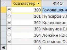
Here is approximately such a set of parts we need to assemble:

LEDs for this device can be used of any type, but always super-bright and different colors of glow. I will be using ultra-bright, highly directional LEDs that will be directed towards the ceiling. You can, of course, use a different lighting option sound signal and use another type of LEDs:

How does it work this scheme . The stereo signal from the sound source enters the input node, which sums the signals from the left and right channels and feeds it to the variable resistances R6, R7, R8, which regulate the signal level for each channel. Next, the signal goes to three active filters assembled according to an identical circuit on transistors VT1-VT3, which differ only in the values of the capacitors. The meaning of these filters is that they pass through themselves only a strictly defined band of the audio signal, cutting off the unnecessary frequency range of the audio signal from above and below. The upper (according to the scheme) filter passes the band 100-800 Hz, the middle one - 500-2000 Hz and the lower one - 1500-5000 Hz. With the help of trimmers R5, R12 and R16, the band to be passed can be shifted in any direction. If you want to get other bandwidths of the filter signal, then you can experiment with the values of the capacitors included in the filters. Further, the signals from the filters are fed to the microcircuits A1-A3 - LM3915. What are microchips.
Chips LM3914, LM3915 and LM3916 from National Semiconductors allow you to build LED indicators with different characteristics - linear, stretched linear, logarithmic, special for audio signal control. In this case, LM3914 is for a linear scale, LM3915 is for a logarithmic scale, and LM3916 is for a special scale. We use LM3915 chips - with a logarithmic scale for monitoring the audio signal.
The initial page of the datasheet of the microcircuit:

(327.0 KiB, 4,279 hits)
In general, I advise you, when faced with a new, unknown radio component, look for its datasheet on the Internet and study it, especially since there are also datasheets translated into Russian.
For example, what can we learn from the first sheet of the LM3915 datasheet (even with minimal knowledge of in English, and in extreme cases using a dictionary):
- this chip is an analog signal level indicator with a logarithmic display scale and a step of 3 dB;
- you can connect both LEDs and LCD indicators;
– indication can be carried out in two modes: “dot” and “column”;
– maximum output current for each LED – 30 mA;
- etc…
By the way, what is the difference between a “point” and a “column”. In the “point” mode, when the next LED is turned on, the previous one goes out, and in the “column” mode, the previous LEDs do not go out. To switch to the “point” mode, it is enough to disconnect pin 9 of the microcircuit from the “+” power source, or connect it to the “ground”. By the way, very useful and interesting circuits can be assembled on these microcircuits.
Let's continue. Since an alternating voltage is applied to the inputs of the microcircuits, the luminous column of LEDs will be with uneven brightness, i.e. with an increase in the input signal level, the next LEDs will not only light up, but also the brightness of their glow will change. Below is a table of the threshold switching on of each LED for different microcircuits in volts and decibels:

Characteristics and pinout of the KT315 transistor:

On this, we finish the first part of the lesson on assembling LED light music and begin to assemble the parts. In the next part of the lesson, we will study the “Cadsoft Eagle” PCB design program and make printed circuit board for our device using film photoresist.
Do-it-yourself color music - what could be more pleasant and interesting for a radio amateur, because it is not difficult to assemble it, having a good scheme.
In modern radio engineering, there is a huge variety of radio elements and LEDs, the advantage of which is difficult to question. Large range of colors, bright and saturated light, high response speed of various elements, low energy consumption. This list of benefits is endless.
The principle of operation of color music: LEDs assembled according to the scheme blink from an existing sound source (it can be a player or a radio tape recorder and speakers) with a certain frequency.
The advantages of using LEDs over those previously used in the CMU:
- light saturation of light and an extensive color range;
- good speed;
- low power consumption.
The simplest schemes
A simple color music that can be assembled has one LED, is powered by a source direct current voltage 6–12 V.
You can assemble the above circuit using an LED strip and selecting the required transistor. The disadvantage is that there is a dependence of the LED flashing frequency on the sound level. In other words, the full effect can be observed only at one sound level. If the volume is lowered, there will be a rare flashing, and when the volume is increased, a constant glow will remain.
You can remove this drawback with the help of a three-channel sound converter. Below is a simple circuit, it is not difficult to assemble it with your own hands on transistors.
 Scheme of color music with a three-channel sound converter
 This circuit requires a 9 volt power supply, which will allow the LEDs in the channels to glow. To assemble three amplifying stages, you will need KT315 transistors (similar to KT3102). As a load, multi-colored LEDs are used. A step-down transformer is used for amplification. Resistors perform the function of adjusting the flashes of the LEDs. The circuit contains filters for passing frequencies.
The diagram can be improved. To do this, add brightness with 12 V incandescent bulbs. You will need control thyristors. The entire device must be powered by a transformer. According to this simplest scheme, you can already work. Color music on thyristors can be collected even by a novice radio technician.

How to make color music on LEDs with your own hands? The first thing to do is to choose an electrical circuit.
Below is a diagram of light music with an RGB tape. This setup requires a 12 volt power supply. It can work in two modes: as a lamp and as a color music. The mode is selected by a switch installed on the board.

Manufacturing steps
You need to make a printed circuit board. To do this, you need to take a foil fiberglass with dimensions of 50 x 90 mm and a thickness of 0.5 mm. The board manufacturing process consists of several stages:
- preparation of foil textolite;
- drilling holes for parts;
- drawing tracks;
- etching.

The board is ready, the components are purchased. Now the most crucial moment begins - the wiring of radio elements. The final result will depend on how carefully they are installed and soldered.

We assemble our printed circuit board with components soldered on it into such an affordable ceiling.

Brief description of radioelements
Radioelements for electrical circuit quite affordable, it will not be difficult to purchase them at the nearest electrical goods store.
For color and musical accompaniment, wire resistors with a power of 0.25–0.125 W are suitable. The resistance value can always be determined by the colored stripes on the body, knowing the order in which they are applied. Trimmer resistors are both domestic and imported.
Industrially produced capacitors are divided into oxide and electrolytic. It will not be difficult to choose the right ones by doing elementary calculations. Some oxide capacitors may have polarity that must be observed during installation.
The diode bridge can be taken ready-made, but if it is not there, then the rectifier bridge is easy to assemble using diodes of the KD or 1N4007 series. LEDs are taken ordinary, with a multi-colored glow. The use of RGB LED strips is a promising direction in radio electronics.
 RGB LED strip
 Possibility of assembling a color and music console for a car
If you managed to please with color music from a do-it-yourself LED strip, then similar installation with a built-in radio can be made for a car. It is easy to assemble and quickly set up. It is proposed to place the prefix in a plastic case, which can be bought in the department of electrical and radio engineering. The unit is reliably protected from moisture and dust. It is easy to install for dashboard car.
Also, a similar case can be made independently using plexiglass.
Plates of the required dimensions are selected, two holes are made in the first of the parts (for power), all parts are sanded. We collect everything with a thermal gun.
An excellent lighting effect is achieved by using multi-colored (RGB) tape.
Conclusion
The well-known saying “not the gods burn the pots” remains relevant today. A diverse range of electronic components gives craftsmen a wide scope for imagination. Do-it-yourself color music on LEDs is one of the manifestations of limitless creativity.
The other day I decided to assemble a color-musical installation. The local club really wanted to add lighting effects. Having rummaged well on the Internet, I found a 3-channel CMU (color-music installation). The circuit does not look complicated, and it turned out to be simple when soldering. And here she is:This 3-channel DMU is very easy to manufacture, but has some disadvantages. This is, firstly, a large required input signal level, secondly, a low input impedance, and thirdly, a sharp flashing of the lamps caused by the lack of compression and the simplicity of the filters used. But as for beginner radio amateurs, the circuit will be just right.

Flash control is performed by thyristors. They can be put in the KU202 series with the letters k, l, m, n. Of course, it is better to take such as in the diagram. Food from a network 220v. Each channel is controlled by variable resistors. The circuit does not need to be configured, it works immediately after proper assembly. When working with color music, keep in mind that you need a sufficiently large music signal.

Transformer TP1 is made on the core Ш16х24 from transformer steel. Winding I contains 60 turns of PEL 0.51 wire. Winding II - 100 turns of PEL 0.51. Any other small-sized transformer (for example, from transistor receivers) with a ratio of turns in the windings close to 1:2 can also be used. Thyristors must be installed on heat sinks if the total lamp power per channel exceeds 200 W.

Collected and checked. Works very well. Here is the device itself in the case:

Here is the arrangement of the elements inside the box I chose. It is better to turn on through a diode bridge. It costs cheap. But I think it’s not important for a radio amateur, but the repetition of the device itself. The circuit can be soldered even by a beginner. The finished color and music device works without interference, a long time of operation does not strain the thyristors. They don't even get hot. Author of the material: Max.
In this article we will talk about color music. Probably, every novice radio amateur, and not only, at one time had a desire to collect color music. What it is, I think, is known to everyone - to put it simply, this creation visual effects changing to the beat of the music.
That part of the color music that emits light can be performed on powerful lamps, for example, in a concert installation, if color music is needed for home discos, it can be done on ordinary 220 volt incandescent lamps, and if color music is planned, for example, as computer modding, for everyday use, it can be done on LEDs.

Recently, with the advent of LED strips on sale, color and music consoles using such led strips are increasingly being used. In any case, for the assembly of Color Musical Installations (CMU for short) a signal source is required, it can be a microphone with several amplifier stages assembled.

Also, the signal can be taken from line out devices, sound card computer, from the output of an mp3 player, etc., in this case you will also need an amplifier, for example, two cascades on transistors, for this purpose I used KT3102 transistors. The preamplifier circuit is shown in the following figure:

Preamplifier - Schematic
The following is a diagram of a single-channel color music with a filter, working in conjunction with a preamplifier (above). In this circuit, the LED blinks under the bass ( low frequencies). To match the signal level in the color music circuit, a variable resistor R6 is provided.

There are more simple circuits color music that any beginner can assemble, on 1 transistor, besides, they do not need a preamplifier, one of these circuits is shown in the picture below:

Color music on a transistor
The pinout diagram of the Jack 3.5 plug is shown in the following figure:

If for some reason it is not possible to collect preamplifier on transistors, you can replace it with a transformer connected as a step-up. Such a transformer should produce voltages on the windings of 220/5 Volts. The winding of the transformer with a smaller number of turns is connected to the sound source, for example, a radio tape recorder, in parallel with the speaker, while the amplifier must produce at least 3-5 watts of power. Winding with large quantity turns is connected to the color music input.
![]()
Of course, color music is not only single-channel, it can be 3, 5 or more multi-channel, when each LED or incandescent lamp flashes when reproducing the frequencies of its range. In this case, the frequency range is set by using filters. In the following scheme, three-channel color music (which I myself recently collected) capacitors are used as filters:

If we wanted to use in the last circuit not individual LEDs, but an LED strip, then the current-limiting resistors R1, R2, R3 should be removed from the circuit. If RGB tape or LED is used, it must be made with a common anode. If you plan to connect led strip long, then powerful transistors mounted on radiators should be used to control the tape.

Since the LED strips are designed for 12 volts, we should raise the power in the circuit to 12 volts, and the power should be stabilized.
Thyristors in color music
So far, the article has only talked about color-music devices based on LEDs. If there is a need to assemble a CMU on incandescent lamps, then thyristors will need to be used to control the brightness of the lamps. What is a thyristor anyway? This is a three-electrode semiconductor device, which accordingly has Anode, Cathode and Control electrode.

KU202 Thyristor
The figure above shows the Soviet thyristor KU202. Thyristors, in case it is planned to be used with a powerful load, must also be mounted on a heat sink (radiator). As we can see in the figure, the thyristor has a thread with a nut and is mounted similarly to powerful diodes. Modern imports are simply equipped with a flange with a hole.

One of these thyristor circuits is shown above. This is a three-channel color music circuit with a step-up transformer at the input. In the case of selecting analogs of thyristors, one should look at the maximum allowable voltage of thyristors, in our case, for KU202N it is 400 volts.

The figure shows a similar scheme of color music given above, the main difference in the lower scheme is that there is no diode bridge. Also, color music on LEDs can be built into system unit. I assembled such a three-channel color music with a preamplifier in a case from a sidirom. In this case, the signal was taken from the sound card of the computer using a signal divider, to the outputs of which active acoustics and color music. Signal level adjustment is provided, both general and separately by channels. The preamplifier and color music were powered from the 12 Volt Molex connector (yellow and black wires). The schemes of the preamplifier and three-channel color music for which they were assembled are given above. There are other color music schemes on LEDs, for example this one, also three-channel:

Color music on 3 LEDs - scheme
In this circuit, unlike the one that I collected, an inductance is used in the medium frequency channel. For those who want to assemble something simpler first, I give the following scheme for 2 channels:

If you collect color music on lamps, you will have to use light filters, which, in turn, can be both home-made and purchased. The figure below shows the filters that are commercially available:

Some lovers of color and musical effects assemble devices based on microcontrollers. Below is a diagram of four-channel color music on the AVR tiny 15 MK:

The Tiny 15 microcontroller in this circuit can be replaced with tiny 13V, tiny 25V. And at the end of the review, on my own behalf, I want to say that color music on lamps loses in terms of entertainment to color music on LED, since lamps are more inertial than LEDs. And for independent repetition, you can recommend this
This is the simplest light music has only one element. Yes, absolutely alone and nothing but: no resistors, no transistors ... It is quite possible to assemble such a light and music installation in 30 minutes. All you need is one solid state relay.
Solid-state relays appeared on the market relatively recently and have already confidently conquered the radio electronics market. It is understandable, I will give the main advantages.
- - Performance.
- - Galvanic isolation by voltage.
- - Silent, compared to a conventional relay.
- - Zero crossing detector.
A solid state relay, in fact, except for the name, has nothing to do with a mechanical relay, which everyone usually imagines when they hear this name for the first time. This is an ordinary triac key, with control and decoupling circuits.
This miracle is quite inexpensive and you can easily buy it on our favorite aliexpress.com
There are a lot of different versions of relays on the radio market: small and large, powerful and low-power. I took this:
First, it has screw terminals for connection. Secondly, it can switch a load with a voltage of 24-380 V and a current of up to 60 A. Of course, I took it with enumeration for other purposes. To control the garland, it is enough to take from 2 A. Thirdly, the control voltage is from 3 to 32 volts, pulsed. That's what we need, since we will control the relay directly by the sound given from the output of the low frequency amplifier.
Scheme of light music

A solid-state relay is switched on to break the circuit of a lamp or garland. And the input of the solid state relay is sound from sound column. The scheme couldn't be simpler. The main thing is not to confuse the conclusions. Now, as soon as the music starts playing in the column, the garland will immediately start flashing to the beat of the music.
We take the output from the amplifier from any channel, left or right. You can connect between outputs to make the garland flash for stereo effect. If there is a subwoofer output, you can connect to it. And you can take two garlands and two relays and connect to different channels. There are many options, pick whichever you like.

I added a park of toggle switches to the circuit, for switching. The first toggle switch in the diagram so that you can simply turn on the garland in normal mode. And the second is to turn off the influence of music on it.
Due to galvanic isolation, high mains voltage securely decoupled and will not cross the speaker and amplifier.
I took a plastic container, placed sockets there to connect the load. I made holes for the toggle switches and connected the entire system.