Troubleshooting methods. As well as the reasons for the inoperability of electronic devices
Name: Troubleshooting in electrical diagrams
Benda Ditmar
Year: 2010 (fast...)
Pages: 250
Format: DjVu
Size: 7.18 MB
Language: Russian (translated from German)
The book summarizes many years of experience practical work and provides proven troubleshooting techniques for various electronic devices. On the in large numbers examples of analog and digital blocks, programmable controllers and computer technology shows a systematic approach and the specifics of troubleshooting in electrical circuits. The basic rules for maintenance, troubleshooting phases, device diagnostics, testing of electronic components are considered.
Table of contents
Foreword
Chapter 1. Basic Rules for Successful Maintenance
1.1. Systematic approach, logic and experience guarantee success
1.2. Communication with the client
Chapter 2 Obtaining information about devices and systems
2.1. Systematic collection of information about the familiar and the unknown
2.2. Collect information purposefully
2.3. Set the characteristic features of the structure
Chapter 3 Systematized troubleshooting in automated devices
3.1. Prerequisites and Sequence for Successful Troubleshooting
3.2. Assessment of the actual state of the device
3.3. Fault area localization
3.4. Repair and commissioning activities
Chapter 4 Determination of polarity and voltage in electronic blocks and circuits
4.1. Voltage measurement
4.2. Faults in the electrical circuit
4.3. The point taken as the reference potential determines the polarity and value of the voltages
4.4. Examples for determining polarity and voltages
4.5. Exercises to consolidate the acquired knowledge
Chapter 5. Systemic troubleshooting in analog circuits
5.1. Determination of voltages in circuits
5.2. Consequences of possible short circuits and breaks at various types connections
Connecting links
Negative feedbacks
Positive Feedback
5.3. Systematized troubleshooting in analog circuits
5.4. Troubleshooting in control and regulation circuits
Three-phase electric drive
Voltage regulator
5.5. Troubleshooting in oscillatory circuits
LC sine wave generator
Bridge RC oscillator
Function Converter
5.6. Troubleshooting Operational Amplifiers
Troubleshooting Preamplifiers
final amplifier
5.7. Exercises to consolidate the acquired knowledge
Chapter 6 System troubleshooting in pulse and digital circuits Oh
6.1. Voltages in digital circuits
6.2. Effects of possible short circuits and internal interruptions
6.3. Systematized search for errors in the digital circuit
6.4. Errors in digital integrated circuits
6.5. Exercises to consolidate the acquired knowledge
Chapter 7 Troubleshooting a system with computer circuits
7.1. Troubleshooting in Tri-State Circuits
7.2. Checking static function parameters
7.3. Checking dynamic function parameters
7.4. Systematized troubleshooting in a computer circuit
7.5. Troubleshooting interface diagrams
7.6. Exercises to consolidate the acquired knowledge
Chapter 8 Troubleshooting Programmable Controller Systems
8.1. Checking static and dynamic function parameters
8.2. Maintenance by diagnostics with a visual display device
8.3. Systematized troubleshooting in the programmable controller circuit
8.4. Exercises to consolidate the acquired knowledge
Chapter 9. Troubleshooting the system with mains voltage nutrition
9.1. Network interference and its effects
9.2. Troubleshooting Rectifier Circuits
9.3. Troubleshooting Power Supplies
9.4. Exercises to consolidate the acquired knowledge
Chapter 10 Finding bugs in testing systems during maintenance and production
10.1. In-Circuit Testing
10.2. Troubleshooting with the Contact Test System
10.3. Preparation of electronic components for testing
10.4. Short circuit localization
10.5. Exercises to consolidate the acquired knowledge
Appendix. Answers to the exercises
Subject index
If you are a professional computer repairer, you should always remember the basic law of business: time is money. Whether you are self-employed or self-employed, your business success will greatly depend on your ability to quickly and confidently identify symptoms and troubleshoot computer and peripheral problems. To do this, you need to have a sharp eye, have common sense and a certain amount of intuition. In addition, you must have a good understanding of the troubleshooting algorithm and clearly plan your actions. The fact is that, despite the almost limitless variety of designs and modifications, as well as options for setting up computers, the methodology for preparing them for repair is almost the same in all situations.
Universal Algorithm troubleshooting
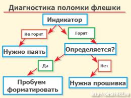
The procedure for diagnosing and localizing faults consists of four main stages: identifying symptoms of a malfunction; identification and localization of the source (or location) of the malfunction; replacement or repair of a suspected node; re-checking the computer to confirm its performance. If the problem cannot be fixed, then the procedure will have to be repeated. The above troubleshooting algorithm is universal, and it can be used when repairing not only computer equipment.
Universal Fault Finding Algorithm
Identification of symptoms.
The reasons for a computer failure can be as simple as a broken wire or poor contact in the connector, or very complex (failure of an integrated circuit or an entire assembly). In any case, before taking up tools, you should carefully analyze the symptoms of a malfunction. Here are the typical questions you should answer first:
Is the removable disk (floppy disk) inserted correctly?
Are the power-on and activity hard disk?
Did the problem occur after something new was connected to the computer (printer, network cable) or just moved it to another place?
The more clearly and fully you imagine the symptoms of a malfunction, the faster and easier you will be able to identify its cause and determine the failed node or component.
It is important to write down all the symptoms that you have to face - at first it may seem like a pointless undertaking. But after some time, when you start repairing another system, you suddenly find in your records such symptoms and circumstances that may not fully correspond to a particular case, but, in any case, will help to significantly narrow the circle of troubleshooting
Fault identification and localization
Before you start troubleshooting the computer hardware, you need to make sure that it is the hardware that is to blame. This is not always obvious, although, of course, there are unambiguous situations (for example, the computer does not turn on, the display screen is blank, etc.). Do not forget that the functioning of a personal computer is a process of close interaction between hardware and software.
An incorrectly installed or configured software component can cause a system error.
When you are convinced that the malfunction occurred precisely at the hardware level, having identified a potential source, you can start repairing!
Repair or replacement
Since the computer and its peripherals are overwhelmingly assembled from functionally complete units, it is almost always easier to replace the entire unit than to try to troubleshoot at the level of its individual components. Even if you have the time, documentation, and diagnostic equipment, many complex assemblies and components are patented, and it will be very difficult to get spare parts for them. The effort and nerves spent in finding and obtaining these parts can cost you more than replacing the entire assembly. The replacement is also supported by the fact that many manufacturers and sellers keep unsold stocks of components and equipment in warehouses for quite a long time. However, keep in mind that often, in order to order and receive a component necessary for repair, you need to know its factory code.
During the repair process, unforeseen complications may arise that will force you to suspend work for a while. In particular, you may have to wait a few days until you receive the parts you ordered. Make it a rule to assemble the repaired system as much as possible before leaving it alone for a while. Pack the remaining parts in plastic bags, seal them and sign them. If you are dealing with electronic components (printed circuit boards), then store them in antistatic packaging (bags or boxes). Partial assembly (as well as detailed notes and careful labeling of components) will save you from doubts and errors when you restore your computer later.
Another problem, created by the rapid technological progress that delights us so much, is that computer components are rarely found on the shelves of stores and warehouses. For example, a video card bought a year ago has almost certainly been discontinued. Quadruple-read speed (4x) CD-ROM drives, considered a marvel of technology a few years ago, can now be bought for pennies, and then only at sales of computer "antiques". Newer models are much faster. Therefore, if the computer fails and the need to replace any node does not exclude the option that it will have to be upgraded - simply because you will not be able to find the necessary spare part. That is why in many cases it is preferable to immediately start upgrading, rather than spend time on diagnostics and repairs.
The most common malfunctions in the electrical circuits of electrical appliances and household appliances:1) break (the resistance of the electrical circuit is equal to infinity);
2) a significant increase in resistance;
3) a significant decrease in resistance;
4) short circuit (the resistance of the electrical circuit is close to zero).
Common causes of these faults:
- breakage due to aging of elements, the passage of increased currents, shock, vibration and corrosion;
- a significant increase in the resistance of electrical circuits compared to the nominal value, caused by aging of the elements, deterioration of contacts and contact connections, deviation of the parameters of individual elements;
- a significant decrease in the resistance of electrical circuits compared to the nominal value due to an increase in surface leakage and aging of the elements.
Short circuits are the result of insulation breakdown, shorting of conductors and elements to the body and to each other (for conductors of different polarities and phases).
When troubleshooting, you need to know and be able to use the signs of proper operation of electrical equipment.
They can be divided into two main groups:
active- indications of light and sound signals, signaling devices, operation of protective equipment, as well as signs detected during measurement by the device;
passive or secondary signs perceived during an external examination of electrical equipment (visual, sound, tactile, olfactory).
Light and sound signals, signaling devices allow you to monitor the status of electrical appliances.
Protective equipment (fuses, maximum or minimum relays, circuit breakers, etc.), when triggered, disconnect electrical circuits from power sources in the presence of increased leakage currents, overload currents and short circuits in the disconnected part of the circuit.
In case of faults - such as a break - the protection usually does not work, but its normal state in the presence of a fault in the electrical circuit is indirect evidence that the damage has the nature of a break.
Troubleshooting is carried out by directional measurements of the parameters of electrical circuit elements using portable devices and measuring kits, using active features.
When measuring the parameters (resistance, current, voltage) of individual elements in electrical circuits (for example, logic control systems, etc.) using portable devices, it is necessary to use maps of resistance, voltage, current at the output of individual elements and blocks, given in the instructions for operation of these devices.
When carrying out special directional measurements in practice, it is used a number of private troubleshooting methods:
-- intermediate measurements, which make it possible to consistently trace the passage of signals through various channels of the system;
- exceptions, which allows, by means of measurements, to exclude serviceable parts of the circuit being checked and to highlight the failed element;
- replacement of blocks (parts) in which the presence of a malfunction is assumed to be of the same type, known to be serviceable;
— Comparison of the test results of the failed circuit with the test results of a serviceable circuit of the same type operating under the same conditions.
In general, troubleshooting consists of the following
stages:
a) establishing the fact of a malfunction of an electrical appliance
to change the active and passive signs of normal operation;
b) analysis of the available signs of malfunctions and their comparison with the possible state of the elements of the electrical appliance;
c) comparison of the symptoms of malfunctions specified in the operating instructions and known from operating experience with the observed symptoms;
d) selection of the optimal search sequence and the volume of additional measurements for examining elements in which faults may occur;
e) sequential measurement;
f) general assessment of the test results and conclusion about the most probable reasons malfunctions of the selected element;
g) Troubleshooting.
The main causes of malfunction of electronic elements are:
--Overcurrent;
--overvoltage;
--increased ambient temperature;
- inadmissible vibration, blows.
In the event of a malfunction or failure of an object (system, device, unit, module, electronic board) it is recommended to start searching for a faulty electronic element after a preliminary check of serviceability:
Signal lamps, fuses, switches and other means of switching and protecting the facility;
Power unit or node of the object by measuring the voltage at the input and output with a voltmeter;
external devices- sensors, signaling devices, limit switches, monitors, kinescopes, acoustic systems etc.
Further search for a faulty element is recommended, taking into account the following guidelines:
The principle of operation of a faulty object must be studied and understood;
First, a more complex faulty object is found, then a simpler one (according to the principle system - block - node - element);
The signs of a malfunction are analyzed, assumptions are made about its causes, and a verification method is selected;
Random inspections of sites are being carried out and individual elements, whose malfunctions are most likely, and their verification takes the least time;
If a faulty element is not detected by a selective check, you should proceed to the search by elimination method, moving from the input to the output of the object, or dividing it before starting the next check into two parts equal in terms of the complexity of the check;
If the malfunction is not typical, then it is advisable, having omitted the selective check stage, to start the search immediately with the elimination method.
It is recommended to enable and disable removable objects for inspection, replacement with spare parts or search for faulty elements when the power supply is off, especially if there are detachable contact connections.
When examining an object, attention must be paid
For violations of protective and insulating coatings;
For discoloration, the presence of darkening, swelling and cracks;
For the serviceability of fasteners, contact surfaces, connections and soldering;
On the temperature of the elements (cases, transistors, resistors, diodes, microcircuits, electrolytic capacitors) immediately after the circuit is turned off.
It must be remembered that the temperature of the housings during normal operation
should not exceed 45-60 ° C - to the touch (the hand does not tolerate the temperature exceeding 60 ° C).
Elements with detected flaws are subject to inspection first.
Determination of a faulty element in an object under voltage is recommended to be performed using serviceable extension cords and adapters, measuring instruments with high internal resistance and instructions available in the documentation about the values and polarity of the potentials.
In the absence of the necessary data, the search can be carried out by comparing the sections of voltages on the same elements of a known good (spare or similar) and faulty objects.
Determination of a faulty element without applying voltage to the object can be carried out by measuring resistance using an ohmmeter in sections or elements, performance
which are in doubt.
If necessary, one or more outputs of the elements can be disabled (soldered).
If the element fails (an increase in leakage current, a decrease in insulation resistance or switching voltage, etc.), it is necessary to measure its main parameters using conventional or special devices and test circuits.
In the absence of the passport data of the element, the measurement results can be compared with similar data of spare known good elements.
In the process of finding, checking and replacing faulty elements (especially semiconductor devices) using the most simple means it is necessary to carefully mark the outputs of the devices.
After detecting a defective element, they analyze possible reasons malfunctions that must be eliminated before replacing it and putting the object into operation.
To increase the reliability of the results, it is recommended to measure the parameters of the elements in a dry room at an air temperature of 20-25 ° C (especially for germanium diodes and transistors).
If the measures taken to inspect and test the faulty object did not lead to the restoration of its operability, and the search for the faulty element did not give a result, the object is subject to transfer to special workshops for repair.
Independent opening and repair of complex objects based on modern semiconductor elements, in the absence of clear instructions in the operating instructions, is not recommended.
Practical methods for troubleshooting in electronic equipment are given without reference to specific equipment. The causes of inoperability are understood as errors of developers, installers, etc. The methods are interconnected and their complex application is almost always necessary. Sometimes search is very closely connected with elimination.
Basic troubleshooting concepts.
1. The action must not harm the DUT.
2. The action must lead to a predictable result:
Putting forward a hypothesis about the serviceability or malfunction of a block, element.
Confirmation or refutation of the hypothesis put forward and, as a result, the localization of the malfunction;
3. It is necessary to distinguish between a probable malfunction and a confirmed (detected malfunction). The proposed hypothesis and the confirmed hypothesis.
4. It is necessary to adequately assess the maintainability of the product. For example, boards with elements in a BGA package have a very low maintainability due to the impossibility or limited possibility of using basic diagnostic methods.
Method description scheme: the essence of the method, the possibilities of the method, the advantages of the method, the disadvantages of the method, the application of the method
1. Clarification of the history of the occurrence of a malfunction. The essence of the method:
The history of the appearance of a malfunction can tell a lot about the localization of the malfunction, about which module is the source of the system's inoperability, and which modules failed as a result of the initial malfunction, about the type of the failed element. Also, knowledge of the history of the occurrence of a malfunction can greatly reduce the time for testing the device, improve the quality of repairs, and the reliability of the corrected equipment. Finding out the history allows you to find out if the malfunction is the result of external influences, such as climatic factors (temperature, humidity, dustiness, etc.), mechanical influences, pollution by various substances, etc.
Examples: if the malfunction at first appeared rarely, and then began to appear more often within a week or several years), then the electrolytic capacitor is most likely faulty, electric lamp or a power semiconductor element, excessive heating of which leads to a deterioration in performance.
If the malfunction appeared as a result of mechanical impact, then it is likely that it will be possible to identify it by external inspection of the unit.
If a malfunction appears with a slight mechanical impact, then its localization should begin with the use of mechanical impacts on individual elements.
Capabilities of the method: The method allows very quickly to put forward a hypothesis about the localization of the fault.
Advantages of the method: there is no need to know the intricacies of the product; efficiency; documentation is not required.
Disadvantages of the method: the need to obtain information about events stretched out in time, at which you were not present, inaccuracy and unreliability of the information provided; in some cases, there is a high probability of error, and inaccuracy of localization; requires confirmation and clarification by other methods.
2. External inspection. The essence of the method:
External inspection is often neglected, but it is the external inspection that allows you to localize about 50% of faults. Especially in the conditions of small-scale production. External inspection in the conditions of production and repair has its own specifics. In production conditions, special attention must be paid to the quality of installation. Installation quality includes: the correct placement of elements on the board, the quality of soldered connections, the integrity of printed conductors, the absence of foreign inclusions in the board material, the absence of short circuits (sometimes short circuits are visible only under a microscope or at a certain angle), the integrity of the insulation on the wires, reliable fastening of contacts in connectors. Sometimes an unsuccessful construct provokes short circuits or breaks.
In terms of repair, you should find out if the device ever worked correctly. If it did not work (a case of a factory defect), then the quality of the installation should be checked. If the device worked normally, but failed (the case of the actual repair), then you should pay attention to traces of thermal damage to electronic components, printed conductors, wires, connectors, etc. Also, during inspection, it is necessary to check the integrity of the insulation on the wires, cracks from time to time, cracks as a result of mechanical stress, especially in places where the conductors work on a kink (for example, sliders and flips of mobile phones). Particular attention should be paid to the presence of dirt, dust, electrolyte leakage and odor. The presence of contaminants may be the reason for the inoperability of the electronic equipment or an indicator of the cause of the malfunction (for example, electrolyte leakage).
In all cases, attention should be paid to any mechanical damage cases, electronic components, boards, conductors, screens, etc. etc.
Method features:
The method allows you to quickly identify a malfunction and localize it to the nearest element.
Advantages of the method: efficiency; exact localization; minimum equipment required; no documentation required (or minimal availability).
Disadvantages of the method: allows you to identify only faults that are manifested in the appearance of the elements and parts of the product; usually requires disassembly of the product, its parts and blocks.
2. Dialing. The essence of the method:
Although this technique has certain disadvantages, it is very widely used in small-scale production, due to its simplicity and efficiency. The essence of the method is that with the help of an ohmmeter, in one form or another, the presence of the necessary connections and the absence of unnecessary connections (short circuits) are checked. In practice, as a rule, it is enough to check the presence of the necessary connections and the absence of short circuits in the power circuits. The absence of unnecessary connections is also ensured by technological methods: marking and numbering of wires in the bundle. A check for the presence of redundant connections is carried out in the case when there is a suspicion of specific conductors, or a suspicion of a design error. Checking for redundant links is extremely time consuming. In this regard, it is carried out as one of the final stages, when a possible closure area (for example, there is no signal at the control point) is localized by other methods. It is possible to localize the short circuit very precisely with the help of a milliohmmeter, with an accuracy of several centimeters.
It is better to call according to the dialing table, compiled on the basis of the electrical circuit diagram. In this case, fix possible mistakes design documentation and ensure that there are no errors in the dialer itself.
Possibilities of the method: prevention of malfunctions during production, quality control of installation; testing the hypothesis about the presence of a fault in a particular circuit.
Advantages of the method: simplicity; high qualification of the performer is not required; high reliability; exact localization of the fault.
Disadvantages of the method: high labor intensity; restrictions when checking boards with mounted elements and connected bundles, elements in the circuit; the need to get direct access to contacts and items.
4. Removal of external performance. The essence of the method.
When applying the method, the product is switched on under working conditions or under conditions simulating working conditions. The characteristics are checked by comparing them with the required characteristics of a serviceable product or theoretically calculated ones.
Capabilities of the method: allows you to quickly diagnose the product; allows you to roughly assess the location of the malfunction, identify the functional unit that does not work correctly, if the product does not work correctly.
Advantages of the method: sufficient high efficiency; accuracy, adequacy; assessment of the product as a whole.
Disadvantages of the method: the need for specialized equipment or, at least, the need to assemble a wiring diagram; the need for standard equipment; the need for a sufficiently high qualification of the performer.
Method application:
For example: On the TV, the presence of an image and its parameters, the presence of sound and its parameters, power consumption, heat dissipation. IN mobile phone on the tester, they check the parameter of the RF path and, by the deviation of certain parameters, they judge the health of the functional blocks. etc.
5. Observation of the passage of signals through cascades.
This method is quite effective. The disadvantages include the complexity and ambiguity of the result.
The essence of the method is that with the help of measuring equipment (oscilloscope, tester, spectrum analyzer, etc.), the correct propagation of signals through the cascades and circuits of the device is observed. In feedback circuits it is very difficult to get unambiguous results, in circuits with a series arrangement of cascades, the loss of the correct signal at one of the control points indicates possible malfunction either an output, or a short circuit at the input, or a communication failure.
At the beginning, the built-in signal sources (clock generators, sensors, power modules, etc.) are isolated and the node in which the signal does not correspond to the correct one, described in the documentation or determined by simulation, is sequentially found. After checking the correct functioning of the built-in signal sources, test signals are applied to the input (or inputs) and the correctness of their distribution and conversion is again monitored. In some cases, for more effective application method requires a temporary modification of the circuit, i.e. if necessary and possible breaking circuits feedback, breaking the connection circuits of the input and output of suspected cascades.
Possibilities of the method: assessment of the performance of the product as a whole; performance evaluation by cascades and functional block.
Advantages of the method: high accuracy fault localization; the adequacy of the assessment of the state of the product as a whole and by cascades.
Disadvantages of the method: great difficulty in estimating feedback circuits; the need for high qualification of the performer.
6. Comparison with a serviceable unit.
Comparison with a serviceable unit is very effective method, because not all characteristics of the product and signals are documented in all nodes of the circuit. The essence of the method lies in the fact that various characteristics of a known good product and a defective one are compared. It is necessary to start the comparison with a comparison appearance, the location of the elements and the configuration of the conductors on the board, the difference in installation indicates that the design of the product has been changed and it is likely that a mistake was made.
Possibilities of the method: operational diagnostics in combination with other methods.
The advantages of the method are quick troubleshooting, there is no need to use documentation.
Disadvantages of the method: the need for a serviceable product, the need for combination with other methods
7. Modeling.
The essence of the method is that the behavior of a serviceable and faulty device is simulated and, based on the simulation, a hypothesis is put forward about a possible malfunction, and then the hypothesis is verified by measurements.
The method is used in combination with other methods to increase their effectiveness.
When troubleshooting an intermittent fault, simulations should be used to determine whether the element being replaced could be causing the fault. For modeling, it is necessary to represent the principles of operation of the equipment and sometimes even know the subtleties of work.
Possibilities of the method: prompt and adequate hypotheses about the localization of the fault.
Advantages of the method: the ability to work with disappearing faults, the adequacy of the assessment.
Disadvantages of the method: a high qualification of the performer is required, a combination with other methods is necessary.
8. Partitioning into functional blocks.
For preliminary localization of a malfunction, it is very effective to break the device into functional blocks. It should be taken into account that often the design division into blocks is not effective from the point of view of diagnostics, since one structural block may contain several functional blocks or one functional block may be structurally made in the form of several modules.
Method capabilities: allows you to optimize the use of other methods.
Advantages of the method: speeds up the troubleshooting process
Disadvantages of the method: deep knowledge of the circuitry of the product is required
9. Temporary modification of the scheme.
Partial disconnection of circuits is used in the following cases:
When chains interact and it is not clear which one is the cause of the malfunction,
When a failed unit can disable other units,
When there is a suspicion that an incorrect/faulty circuit is blocking the operation of the system
Care must be taken when disabling protection circuits and negative feedback circuits, as disabling them may cause significant damage to the product. Disabling feedback circuits can lead to a complete disruption of the cascade operation mode and, as a result, not give the desired result. Opening the POS circuit in generators naturally leads to a disruption in generation, but can allow you to remove the characteristics of the cascades.
Possibilities of the method: localization of faults in circuits with OS, exact localization of faults.
Advantages of the method - allows you to more accurately localize the fault.
Disadvantages of the method: the need to modify the system, the need to know the intricacies of the device.
10. Turning on the functional block outside the system, under conditions modeling the system. In fact, the method is a combination of methods: splitting into functional blocks and taking external performance characteristics.
When faults are detected, the “suspect” block is checked outside the system, which allows either narrowing the search circle if the block is healthy, or localizing the fault within the block if the block is faulty. When applied this method it is necessary to monitor the correctness of the conditions created and the tests applied. Blocks can be poorly coordinated with each other at the development stage.
Possibilities of the method: verification of the hypothesis about the performance of a particular part of the system.
Advantages of the method: the possibility of testing and repairing a functional unit without a system.
Disadvantages of the method: the need to assemble a verification scheme
11. Preliminary check of functional blocks.
It is widely used to prevent system malfunctions in the production of new products. Function block is preliminarily checked outside the system, on a specially made stand (workplace).
When repairing, the method makes sense if the block does not require too many inputs, or in other words, it is not too difficult to simulate the system. For example, this method makes sense to apply when repairing power supplies.
12. Replacement method.
The suspect block/component is replaced with a known good one. And the functioning of the system is checked. Based on the results of the test, the correctness of the hypothesis regarding the malfunction is judged. Several cases are possible:
When the behavior of the system has not changed, this means that the hypothesis is not true.
When all the malfunctions in the system are eliminated, then the malfunction is really localized in the replaced unit
When some of the defects have disappeared, this may mean that only a secondary malfunction has been eliminated and the serviceable unit will burn out again under the influence of the primary system defect. In this case, perhaps the best solution is to re-install the replaced unit (if possible and appropriate) and continue troubleshooting in order to eliminate exactly the root cause.
For example, a power supply failure can cause several units to fail, one of which will fail due to overvoltage.
13. Checking the operating mode of the element.
The essence of the method is that they check the conformity of currents and voltages in the circuit, supposedly correct, reflected in the documentation, calculated during simulation, obtained during the study of a serviceable unit. Based on this, a conclusion is made about the serviceability of the element.
The correctness of the logical levels of digital circuits (compliance with standards, and also compared with ordinary, typical levels), check the voltage drops across diodes, resistors (compare with the calculated or with the values in a working unit).
14. Provoking influence.
Increase or decrease in temperature, humidity mechanical effect. Such actions are very effective in detecting intermittent faults.
15. Check element temperature.
The essence of the method is simple, any measuring instrument(or with your finger) you need to estimate the temperature of the element or draw a conclusion about the temperature of the element by indirect signs (tint colors, burning smell, etc.). Based on these data, a conclusion is made about a possible malfunction of the element.
16. Execution of test programs.
The essence of the method is that a test program is executed on a running system that interacts with various components of the system and provides information about their response, or a system controlled by a test program controls peripheral devices and the operator observes the response peripherals, or a test program allows you to observe the response of peripheral devices to a test action (pressing a key, the reaction of a temperature sensor to a temperature change, etc.).
The method is applicable only for final testing and elimination of very minor flaws.
The method has significant drawbacks. to execute the test program, the system core must be in good condition, an incorrect response does not allow accurate localization of the fault (both the periphery and the system core, as well as the test program, may be faulty).
The advantages of the method include a very fast assessment according to the criterion works - does not work.
17. Step-by-step execution of commands.
This method can be classified as one of the varieties of the “test program execution method”, but the method can be applied on an almost inoperable system. The method is very efficient for debugging microprocessor systems at the development stage.
The disadvantages of the method include a very high labor intensity. Very much to the merits low cost the necessary equipment.
18. Test signatures.
19. "Exit to the entrance."
If the product/system has an output (multiple outputs) and has an input (multiple inputs) and the input/output can operate in duplex mode, then it is possible to check the system in which the signal from the output, through external links given to the entrance. The presence/absence of the signal, its quality is analyzed, and based on the results, an assessment is made of the performance of the corresponding circuits.
20. Typical malfunctions.
21. Analysis of the impact of a malfunction.
Damage in electrical circuits of cranes
Tower Crane Electrical Equipment consists of a huge number
electric motors, electronic apparatus and devices connected to each other
wiring, the length of which achieves several thousand meters. In progress
crane operation, damage may occur in electronic circuits. These damages
can be caused by the failure of parts of machines and apparatus, breakage
wiring and insulation damage.
Ways to eliminate defects in the electronic circuits of cranes
Electronic circuit malfunctions are eliminated in two steps. At first they seek
faulty section of the circuit, and then restore it. More difficult 1st
step. Ability to identify the fault location in a shorter time and with
lower labor costs is of very fundamental importance, because it allows
significantly reduce crane downtime. Restoration of the damaged area is usually
comes down to replacing a defective element (contact, coil, wire) or
broken wire connection.
Malfunctions of electronic circuits can be divided into four groups:
electronic circuit; short circuit in the circuit; short circuit to the body (breakdown
isolation); the appearance of a bypass circuit when the wires are shorted together.
All these malfunctions can have different external manifestations, depending on
from the features of the electronic circuit of the crane. Therefore, when troubleshooting
it is necessary to painstakingly analyze the operation of the circuit in various modes, to identify
differences in the operation of individual crane devices and only then proceed to
looking for damage in that part of the circuit that can cause these differences.
It is impossible to give a methodology applicable for searching for any type of malfunction,
since even monotonous drive schemes for various devices cranes have their own
peculiarities. But some general rules can be applied in the analysis
any crane wiring diagram.
First, it is determined in which circuit - power or control - appeared
malfunction.
Consider an example of a malfunction of the drive electronic circuit
mechanism for turning the crane S-981A. The problem is that the mechanism
turn is not cut in the direction to the left. All other mechanisms, including
and the turning mechanism in the direction to the right, work.
If during the trial inclusion of the handle of the controller in the 1st position
The magnetic starter K2 does not turn on to the left (Fig. 1, a), the malfunction follows
find in the control circuit, i.e. in the coil circuit of this starter (circuit: wire 27,
contact B1-3 of the starter K2 and jumpers between the main contacts of the starter K2 and
starter K1.

Rice. 1. Search for a fault in the electronic circuit of the turn drive
crane S-981A;
a - a circuit diagram of the drive turning the crane;
b - mounting electronic circuit of a reversible magnetic starter; /, //,
///, IV - the sequence of turning on the voltmeter when checking the circuit
The break point can be found by checking the circuit with a voltmeter or
indicator lamp that turn on as shown in the picture. 1st
switching on serves to control the operation of the voltmeter itself (pilot lamp).
Assume that when a voltmeter is connected to terminal 31, it indicates the voltage
(the lamp is lit), but does not indicate when connected to terminal 51. As it should, break
located between these terminals. The figure shows that this area includes
limit switch VK2 and wires connecting it to the cabinet terminals
management.
Using this method to identify the location of an open circuit, you must strictly
observe the rules of electrical safety: work in dielectric gloves and
galoshes or, standing on an insulating stand, do not touch the contacts and
naked conductors.
When used to check the pilot lamp
take constructive measures against the inclusion of the magnetic starter K2 and the rotation mechanism
crane. To do this, fix the anchor of the magnetic starter in the Off position.
The lamp in a cool state has a small resistance (a couple of times
smaller than the second lamp) and when connected to terminal 31 appears
closed circuit (wire 27, control lamp, coil K2, wire 28), which
triggers starter K2. When using a voltmeter, the starter does not
may turn on, because the voltmeter winding has a huge resistance.
When checking the circuit to determine the location of the break, you should keep in mind that many
cranes, part of the circuit operates on alternating current, and part on constant current. When checking the DC circuit, the terminals
voltmeter (lamp) is connected to a constant current source, and when checking the circuit
alternating current- to the AC phase. During work, be sure to
use electronic circuits, because the incorrect inclusion of the lamp in phase
alternating current when checking a circuit operating at constant current, can
cause damage to the rectifiers.
When searching for a short circuit to the case (insulation breakdown), a section (with
supposed breakdown) is disconnected from the current source, and the voltmeter (lamp)
connected to the current source and the tested area. In normal state
the disconnected section is isolated from the metal structure of the crane and the voltmeter (lamp)
will show nothing. During breakdown, the voltmeter indicates voltage, and the lamp glows.
Alternately disconnecting the individual parts of the tested section of the circuit, you can
find the damaged area.
If, for example, in coil K2 (see Fig. 1) the insulation has been pierced, then when you turn off
coil from drive 28 and connecting a voltmeter to terminals 27 and 51 (terminal B1-3
controller is open) the voltmeter will show voltage.
It is much more efficient and safer to create a circuit check using
ohmmeter or probe. The probe consists of a millivoltmeter with a measurement limit
0-75 mV, connected in series with a resistor R = 40 - 60 Ohm and a battery 4.5
In from a flashlight. Probe leads A and B are used to connect to the terminals
tested circuit. The troubleshooting procedure is similar to that described a little higher,
but the tap is disconnected from the external network, because the ohmmeter and probe have their own
current sources.
When using an ohmmeter or a probe, the possibility of
electric shock, in addition, with the help of them you can find a place of a short
wire shorts.

Line contactor control circuits (protection circuits) for various types of cranes
performed according to general principle, they differ only in the number of
turned on devices and have general symptoms of a malfunction. Every chain of defense
can be conditionally divided into three sections: a section with zero contacts
controllers and a button to turn on the line contactor; block blocking area
zero contacts of controllers and a button when the contactor is turned on and closed
auxiliary contacts (blocking circuit); common area, which includes emergency
switches, contacts of the largest relays and the coil of the line contactor.
An external sign of an open circuit in each section is a certain disposition.
operation of the line contactor. When the circuit is broken in the first section, the linear
the contactor does not turn on when the button is pressed, but turns on when
manually turn the movable part of the contactor until the auxiliary contacts close. At
test switching on the contactor - manual follow-up measures must be taken
safety: set all controllers to zero position; turn
movable part of the contactor or using a fitting tool with
insulated handles or insulated gloves.
If the circuit is broken in the second section, the line contactor cuts in at
when the button is pressed, but disappears when the button returns to normal
position.
When the circuit is broken in the 3rd section, the line contactor does not turn on either.
from the button, nor when manually moving it to the on position.
Motor failures
From various fault circumstances
electric motors we will focus on the more common ones.
A short circuit in the rotor winding. Symptom: Turn on
the motor is abrupt, the motor speed does not depend on the position
controller. To check, disconnect the motor rotor from the ballast
resistance. If, when the stator is turned on, the engine will work, the winding
rotor is shorted.
A short circuit in the stator winding. Symptom: engine
when turned on, it does not spin, the greatest protection is activated.
Breakage of one of the stator phases when the motor is connected by a star. signs
malfunctions: the engine does not make torque and, as it should,
mechanism does not rotate. To find a fault, the engine
disconnected from the network and each phase is individually inspected with a test lamp.
For testing, use low voltage (12 V). If there is no break, the lamp will
glow with full heat, and when checking a phase that has a break, the lamp does not glow
will.
Break in the circuit of one phase of the rotor. Symptom: The engine spins with
half speed and very humming. In the event of a phase failure of the stator or rotor,
motor cargo and boom winch can be dropped cargo (boom)
regardless of the direction in which the controller is turned on.